Page 750 of 2893
���� �µ�µ
F Clutch Pedal Height:
Except Type S model: 159.3 mm (6.27 in.)
Type S model: 161.3 mm (6.35 in.)
G Clutch Pedal Stroke: 130 140 m")
��������
�(�#�'���������������
�
�����
�������
�"�����)���� �µ�µ
F Clutch Pedal Height:
Except Type S model: 159.3 mm (6.27 in.)
Type S model: 161.3 mm (6.35 in.)
G Clutch Pedal Stroke: 130 140 mm (5.12 5.51 in.)
12-8Clutch
Clutch Pedal, Clutch Pedal Position Switch, and Clutch Interlock Switch
Adjustment
B
A F
G
A
D E
B
C
NOTE: For a cruise control problem, check the clutch pedal position switch (see page 4-50).
For an engine cranking problem, check the clutch interlock switch (see page 4-8).
The clutch is self-adjusting to compensate for wear.
If there is no clearance between the master cylinder piston and the pushrod, the release bearing will be
held against the diaphragm spring, which can result
in clutch slippage or other clutch problems.
1. Lift up the carpet (A). At the insulator cutout, measure pedal height from the right side of the
pedal pad (B). 2. Loosen the clutch pedal position switch locknut (A),
and back off the clutch pedal position switch (B)
until it no longer touches the clutch pedal (C).
3. Loosen the clutch pushrod locknut (D), and turn the pushrod (E) in or out to get the specified height (F)
and stroke (G) at the clutch pedal. If adjusting the
pushrod causes the clutch pedal to contact the
clutch pedal position switch, back off the switch
further.
08/08/21 14:42:30 61SNR030_120_0010
ProCarManuals.com
DYNOMITE -2009-
Page 751 of 2893
 C
9.8 N·m
(1.0 kgf·m,
7.2 lbf·ft)
B A
9.8 N·m
(1.0 kgf·m,
7.2 lbf·ft)
B
912mm
(0.35 0.47 in.)
4. Tighten the clutch pushrod")
�µ�µ
�����
�����
�µ
�µ
12-9
A
18 N·m
(1.8 kgf·m,
13 lbf·ft) C
9.8 N·m
(1.0 kgf·m,
7.2 lbf·ft)
B A
9.8 N·m
(1.0 kgf·m,
7.2 lbf·ft)
B
912mm
(0.35 0.47 in.)
4. Tighten the clutch pushrod locknut (A).
5. With the clutch pedal released, turn in the clutch pedal position switch (B) until it contacts the clutch
pedal.
6. Turn in the clutch pedal position switch an additional 3/4 to 1 turn. Make sure the clutch pedal
height did not change.
7. While holding the clutch pedal position switch, tighten the locknut (C). 8. Loosen the clutch interlock switch locknut (A).
9. Fully press the clutch pedal to the floor, then
release the clutch pedal 9 12 mm (0.35 0.47 in.)
and hold it there.
10. Adjust the position of the clutch interlock switch (B), so the engine starts with the clutch pedal in this
position.
11. While holding the clutch interlock switch, tighten the locknut.
12. Check the clutch operation.
13. Connect the clutch pedal position switch connector and the clutch interlock switch connector, then
check the cruise control and the engine starting.
08/08/21 14:42:30 61SNR030_120_0011
ProCarManuals.com
DYNOMITE -2009-
Page 752 of 2893
����
Special Tools Required
Pressure Plate Inspection and Removal
Standard (New): 0.6 mm (0.02 in.) max.
Service Limit: 0.8 mm (0.03 in.)")
���
����
����
�(�#�'���������������
�
��������������� �����)����
Special Tools Required
Pressure Plate Inspection and Removal
Standard (New): 0.6 mm (0.02 in.) max.
Service Limit: 0.8 mm (0.03 in.)
Engine Side
12-19
Clutch Replacement
A
07JAF-PM7011A
C
07936-3710100 B
07ZAF-PR8A100 DC
07936-3710100
A
07LAB-PV00100B
07ZAF-PR8A100
D E
A
Clutch alignment disc 07JAF-PM7011A
Ring gear holder 07LAB-PV00100
Clutch alignment shaft 07ZAF-PR8A100
Bearing remover shaft 07936-KC10500
Slide hammer 07741-0010201
Bearing driver attachment, 22 x 24 mm 07746-0010800
Driver handle, 15 x 135L 07749-0010000
Remover handle 07936-37101001. Remove the transmission; 5-speed model (see page 13-7), 6-speed model (see page 13-84).
2. Check the evenness of the height of the diaphragm spring fingers using the clutch alignment disc (A),
the clutch alignment shaft (B), the remover handle
(C), and a feeler gauge (D). If the height is more
than the service limit, replace the pressure plate. 3. Install the ring gear holder (A), the clutch alignment
shaft (B), and the remover handle (C).
4. To prevent warping, loosen the pressure plate mounting bolts (D) in a cri sscross pattern in several
steps, then remove the pressure plate (E).
5. Inspect the fingers of the diaphragm spring (A) for wear at the release bearing contact area.
(cont’d)
08/08/21 14:42:50 61SNR030_120_0021
ProCarManuals.com
DYNOMITE -2009-
Page 755 of 2893

A
07LAB-PV00100
B
K20Z2enginemodel:
12x1.0mm
103 N·m")
������
�� ���
�����
�µ�µ
Crankshaft Pilot Bushing Inspection Crankshaft Pilot Bushing Replacement
12-22Clutch
Clutch Replacement (cont’d)
A
07LAB-PV00100
B
K20Z2enginemodel:
12x1.0mm
103 N·m
(10.5kgf·m,76lbf·ft)
K20Z3enginemodel:
122 N·m
(12.5kgf·m,90lbf·ft) B
07936-KC10500C
07741-0010201
A
C
07746-0010800
B
07749-0010000
2.4 2.6 mm (0.09 0.10 in.)
A
18. Install the flywheel on the crankshaft, and install
the mounting bolts finger-tight.
19. Install the ring gear holder (A), then torque the flywheel mounting bolts (B) in a cri sscross pattern
in several steps.
20. Inspect the crankshaft pilot bushing for wear and damage.
21. Inspect the inside surface of the crankshaft pilot bushing with your finger. If the crankshaft pilot
bushing is not smooth, replace it; then go to step
22. 22. Remove the crankshaft pilot bushing (A) using the
bearing remover shaft (B) and the slide hammer (C).
23. Install a new crankshaft pilot bushing (A) into the crankshaft using the 15 x 135L driver handle (B)
and the 22 x 24 mm bearing driver attachment (C).
08/08/21 14:42:53 61SNR030_120_0024
ProCarManuals.com
DYNOMITE -2009-
Page 776 of 2893
���
Fluid Capacity
1.5 L (1.6 US qt) at fluid change
1.7 L (1.8 US qt) at overhaul
13-5
Transmission Fluid Inspection and Replacement
A B")
����
������(�#�'���������������
���������
�����
�"�����)���
Fluid Capacity
1.5 L (1.6 US qt) at fluid change
1.7 L (1.8 US qt) at overhaul
13-5
Transmission Fluid Inspection and Replacement
A B
C
C
44 N·m
(4.5 kgf·m,
33 lbf·ft)
A
39 N·m
(4.0 kgf·m,
29 lbf·ft)
B D
1. Raise the vehicle on a lift.
2. Remove the filler plug (A) and the sealing washer
(B). Check the condition of the MTF, and make sure
it is at the proper level (C).
3. If the MTF is dirty, remove the drain plug (A) and the sealing washer (B), and drain it.
4. Install the drain plug with a new sealing washer, and refill the transmission with MTF to the proper
level. Always use Acura Manual Transmission Fluid
(MTF).
5. Install the filler plug (C) with a new sealing washer (D). 6. If the maintenance minder required to replace the
MTF, reset the maintenance minder (see page 3-4).
If it did not reset, go to step 7.
7. Connect the Honda Diagnostic System (HDS) to the data link connector (DLC) (see step 2 on page 11-3).
8. Turn the ignition switch to ON (II).
9. Make sure the HDS communicates with the vehicle and the engine control module (ECM). If it does not
communicate, go to the DLC circuit troubleshooting
(see page 11-204).
10. Select BODY ELECTRICAL with the HDS.
11. Select ADJUSTMENT in the GAUGES MENU with the HDS.
12. Select RESET in the MAINTENANCE MINDER with the HDS.
13. Select MAINTENANCE SUB ITEM 3, and reset the MTF life with the HDS.
Replace. Replace.
08/08/21 14:44:17 61SNR030_130_0007
ProCarManuals.com
DYNOMITE -2009-
Page 778 of 2893
����
Special Tools Required
13-7
Transmission Removal
A
B C
D
A A
B
A
B C
Engine hanger adapter
VSB02C000015
2006 Civic engine")
�Ì
�Ï
���
����
����
�(�#�'���������������
�����
����������� �����)����
Special Tools Required
13-7
Transmission Removal
A
B C
D
A A
B
A
B C
Engine hanger adapter
VSB02C000015
2006 Civic engine hanger VSB02C000025
Engine support hanger, A and Reds AAR-T 1256
Front subframe adapter VSB02C000016
These special tools are available through the Acura
Canada Technical Tools Department; FAX
866-398-8665/e-mail: ch_technicaltools ch.honda.com
NOTE: Use fender covers to avoid damaging painted
surfaces.
1. Do the battery removal procedure (see page 22-69).
2. Remove the cowl cover and the under-cowl panel (see page 20-163).
3. Remove the air cleaner assembly (see page 11-345).
4. Remove the harness clips (A) and the intake air duct (B), then remove the battery base (C) with the
coolant reservoir (D). 5. Remove the clutch line bracket (A), then carefully
move the slave cylinder (B) out of the way to avoid
bending the clutch line.
NOTE: Do not press the clutch pedal after the slave
cylinder has been moved.
6. Disconnect the back-up light switch connector (A), the output shaft (countershaft) speed sensor
connector (B), and the harness clips (C).
(cont’d)
08/08/21 14:44:19 61SNR030_130_0009
ProCarManuals.com
DYNOMITE -2009-
Page 780 of 2893
�����
���������
�
��
13-9
A
B
C
VSB02C000015 VSB02C000025
AAR-T1256
A D
B
C
10. Remove the engine wire harness cover (A) by lifting up on the lock tab (B), then slide the harness
cover forward off the bracket (C).
11. Attach the engine hanger adapter (VSB02C000015) to the threaded holes in the cylinder head. 12. Install the front leg assembly (A), the hook (B), and
the wingnut (C) from an A and Reds engine support
hanger (AAR-T1256) onto the 2006 Civic engine
hanger (VSB02C000025). Carefully position the
engine hanger on the vehicle, and attach the hook
to the forward hole in the engine hanger adapter
(D). Tighten the wingnut by hand to lift and support
the engine/transmission assembly.
NOTE: Use care when working around the
windshield.
13. Remove the two upper transmission mounting bolts.
(cont’d)
08/08/21 14:44:21 61SNR030_130_0011
ProCarManuals.com
DYNOMITE -2009-
Page 781 of 2893
�
�
�
���
��
����
13-10Manual Transmission
Transmission Removal (cont’d)
A
B
B
B
A
B A
B
C
DB
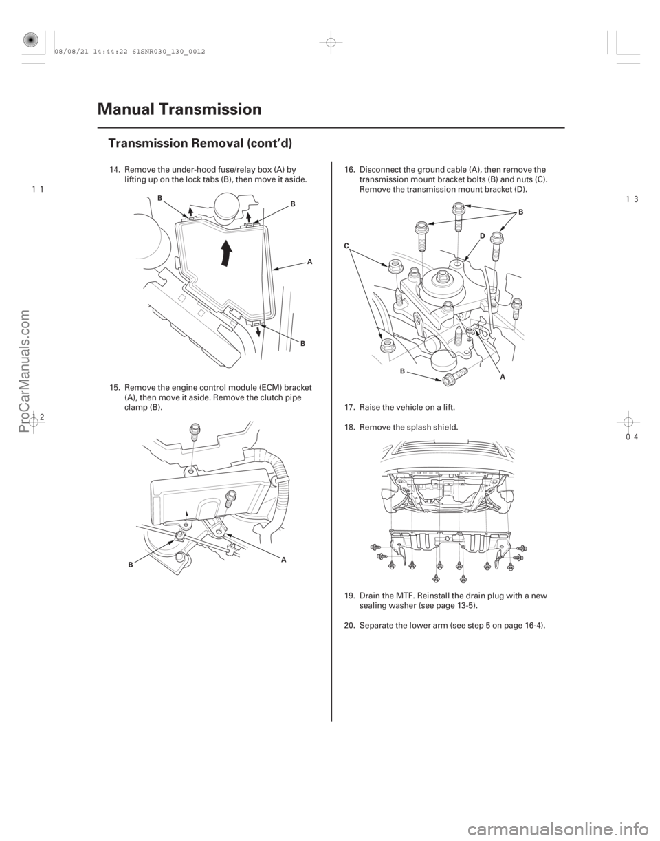
14. Remove the under-hood fuse/relay box (A) by
lifting up on the lock tabs (B), then move it aside.
15. Remove the engine control module (ECM) bracket (A), then move it aside. Remove the clutch pipe
clamp (B). 16. Disconnect the ground cable (A), then remove the
transmission mount bracket bolts (B) and nuts (C).
Remove the transmission mount bracket (D).
17. Raise the vehicle on a lift.
18. Remove the splash shield.
19. Drain the MTF. Reinstall the drain plug with a new sealing washer (see page 13-5).
20. Separate the lower arm (see step 5 on page 16-4).
08/08/21 14:44:22 61SNR030_130_0012
ProCarManuals.com
DYNOMITE -2009-