Page 1458 of 2893
�����
18-46Rear Suspension
Spring Replacement (cont’d)
A
B
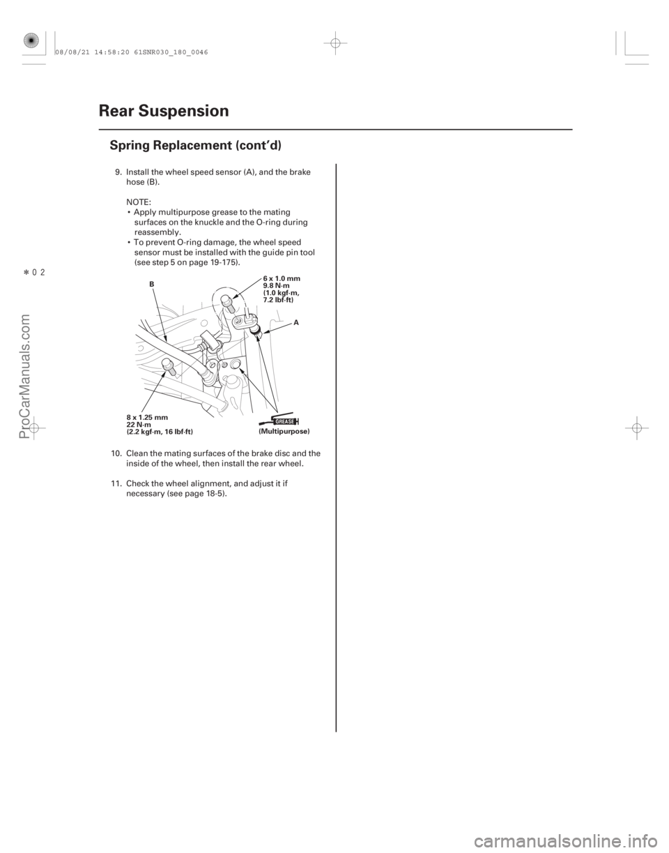
6x1.0mm
9.8 N·m
(1.0 kgf·m,
7.2 lbf·ft)
8x1.25mm
22 N·m
(2.2 kgf·m, 16 lbf·ft) (Multipurpose)
9. Install the wheel speed sensor (A), and the brake
hose (B).
NOTE: Apply multipurpose grease to the mating surfaces on the knuckle and the O-ring during
reassembly.
To prevent O-ring damage, the wheel speed sensor must be installed with the guide pin tool
(see step 5 on page 19-175).
10. Clean the mating surfaces of the brake disc and the inside of the wheel, then install the rear wheel.
11. Check the wheel alignment, and adjust it if necessary (see page 18-5).
08/08/21 14:58:20 61SNR030_180_0046
ProCarManuals.com
DYNOMITE -2009-
Page 1473 of 2893

Control Unit
(With Radio Frequecy Antenna)
Tire Pressure Sensor
(Sensor-transmitter with acceleration sensor)
When the vehicle is tr")
����
System Communication
18-60TPMS
System Description (cont’d)
Control Unit
(With Radio Frequecy Antenna)
Tire Pressure Sensor
(Sensor-transmitter with acceleration sensor)
When the vehicle is traveling more than 45 km/h (28 mph), an RF (radio frequency) band wave signal is transmitted
from each tire pressure sensor to the control unit.
When the wheels rotate, and the tire pressure sensors momentum is detected, switching them from sleep mode to normal function (awake) mode. After the vehicle is stationary for 5 minutes, the sensors switch from normal
function mode back to sleep mode to extend their battery life.
Each tire pressure sensor has its own ID to prevent jamming by similar systems on other vehicles. After memorizing all the sensor IDs, the control unit recognizes only those specific signals.
An ID cannot be memorized automatically. The control unit knows which ID belongs to each tire pressure sensor. This recurring ID confirmation prevents any confusion in the system as a result of normal tire rotation.
NOTE: Be careful not to bend the brackets on the TPMS control unit: Misalignment of the control unit could interfere
with sending and receiving signals.
08/08/21 14:58:25 61SNR030_180_0060
ProCarManuals.com
DYNOMITE -2009-
Page 1587 of 2893

B
A
A
07AAG-SVBA100 B
07AAG-SVBA100
A
4. Apply multi-purpose grease to the wheel speedsensor O-ring (A) and the sen")
�����
����������
19-94ABS Components
Wheel Speed Sensor Replacement (cont’d)
B
A
A
07AAG-SVBA100 B
07AAG-SVBA100
A
4. Apply multi-purpose grease to the wheel speedsensor O-ring (A) and the sensor hole in the knuckle
(B).
5. Insert the guide pin tool (A) into the wheel speed sensor bolt hole until the shoulder of the tool
contacts the wheel speed sensor bracket.
NOTE: To prevent O-ring damage, the wheel speed
sensor must be installed with the guide pin tool. 6. Insert the wheel speed sensor (A) and the guide pin
tool (B) into the bolt hole on the knuckle.
NOTE: To ensure proper alignment when pushing
the wheel speed sensor into the knuckle housing,
do not hold the sensor bracket during installation,
hold the sensor wire.
7. Gently push and pull the wheel speed sensor in and out to make sure the O-ring is sliding properly in its
housing. While you are doing this, make sure the
sensor doesn’t come out of the knuckle assembly. If
the sliding effort is too high, remove the wheel
speed sensor, inspect the O-ring for damage, and
start the installation process again.
8. Remove the guide pin tool, then install the bolt, and tighten it to specified torque.
9. Clean the mating surfaces between the brake disc and the inside of the wheel, then install the front
wheel.
10. Start the engine, and make sure the ABS indicators go off.
11. Test-drive the vehicle, and make sure the ABS indicators do not come on.
08/08/21 15:04:46 61SNR030_190_0094
ProCarManuals.com
DYNOMITE -2009-
Page 1667 of 2893
 and the sensor hole in the knuckle
(B).
5. Insert the guide pin to")
�����
����������
19-175
A
B
A
07AAG-SVBA100 B
07AAG-SVBA100
A
4. Apply multi-purpose grease to the wheel speedsensor O-ring (A) and the sensor hole in the knuckle
(B).
5. Insert the guide pin tool (A) into the wheel speed sensor bolt hole until the shoulder of the tool
contacts the wheel speed sensor bracket.
NOTE: To prevent O-ring damage, the wheel speed
sensor must be installed with the guide pin tool. 6. Insert the wheel speed sensor (A) and the guide pin
tool (B) into the bolt hole on the knuckle.
NOTE: To ensure proper alignment when pushing
the wheel speed sensor into the knuckle housing,
do not hold the sensor bracket during installation,
hold the sensor wire.
7. Gently push and pull the wheel speed sensor in and out to make sure the O-ring is sliding properly in its
housing. While you are doing this, make sure the
sensor doesn’t come out of the knuckle assembly. If
the sliding effort is too high, remove the wheel
speed sensor, inspect the O-ring for damage, and
start the installation process again.
8. Remove the guide pin tool, then install the bolt, and tighten it to specified torque.
9. Clean the mating surfaces between the brake disc and the inside of the wheel, then install the front
wheel.
10. Start the engine, and make sure the ABS and the VSA indicators go off.
11. Test-drive the vehicle, and make sure the ABS and the VSA indicators do not come on.
08/08/21 15:06:48 61SNR030_190_0175
ProCarManuals.com
DYNOMITE -2009-
Page 2693 of 2893
����
General PrecautionsSteering-related Precautions
Cable Reel Alignment
24-13
Precautions and Procedures
NOTE: Some systems store data in memory tha")
���
�(�#�'���������������������������������������)����
General PrecautionsSteering-related Precautions
Cable Reel Alignment
24-13
Precautions and Procedures
NOTE: Some systems store data in memory that is lost
when the battery is disconnected. Before disconnecting
the battery, refer to Battery Terminal Disconnection and
Reconnection (see page 22-68).
Please read the following precautions carefully before
servicing the airbag system. If the instructions
described in this manual are not properly followed, or
the airbags could accidentally deploy and cause
damage or injuries. Except when doing electrical inspections, always turn the ignition switch to LOCK (0), disconnect the
negative cable from the battery, then wait at least
3 minutes before starting work.
NOTE: The SRS memory is not cleared even if the
ignition switch is turned to LOCK (0), or the battery
cables are disconnected from the battery.
Use replacement parts which are manufactured to the same standards and quality as the original parts. Do
not install used SRS parts. Use only new parts when
making SRS repairs.
Carefully inspect any SRS part before you install it. Do not install any part that shows signs of being
dropped or improperly handled, such as dents, cracks
or deformation.
Before disconnecting the SRS unit connectors, always disconnect the appropriate SRS parts
connectors. Use only a digital multimeter to check the system. If it
is not a Honda multimeter, make sure its output is
10 mA (0.01 A) or less when switched to the lowest
value in the ohmmeter range. A tester with a higher
output could cause accidental deployment and
possible injury.
Do not put objects on the front passenger’s airbag.
The original audio and navigation system have a coded theft protection circuit. Make sure you have the
anti-theft codes for the audio system or navigation
system (if equipped), then write down the audio
presets before disconnecting the negative cable from
the battery.
Before returning the vehicle to the client, enter the anti-theft codes for the audio system or navigation
system (if equipped), then enter the audio presets; set
the clock.
Misalignment of the cable reel could cause an open in the wiring, making the SRS system, remote steering
wheel controls, or the horn inoperative. Center the
cable reel whenever you do the following (see step 6
on page 24-202).
– Installation of the steering wheel
– Installation of the cable reel
– Installation of the steering column
– Other steering-related adjustment or installation
Do not disassemble the cable reel.
Do not apply grease to the cable reel.
If the cable reel shows any signs of damage, replace it with a new one. For example, if the cable reel does
not rotate smoothly, replace it.
(cont’d)
08/08/21 13:54:18 61SNR030_240_0013
ProCarManuals.com
DYNOMITE -2009-