Page 879 of 2893

����
���������
�
�
�µ�µ
�µ�µ �µ�µ
�µ�µ
Standard: 23.92 23.97 mm (0.942 0.944 in.)
Service Limit: 23.80 mm (0.937 in.)
Standard: 0.06 0.16 mm (0.002 0.006 in.)
Service Limit: 0.25 mm (0.010 in.) Standard: 24.03 24.08 mm (0.946 0.948 in.)
Standard: 23.92 23.97 mm (0.942 0.944 in.)
Service Limit: 23.80 mm (0.937 in.)
13-110Manual Transmission
Mainshaft Assembly Clearance Inspection (cont’d)
A
B
C
9. Measure the thickness of 5th gear.
If the thickness is less than the service limit,replace 5th gear.
If the thickness is within the service limit, replace the 5th/6th synchro hub and the 5th/6th synchro
sleeve as a set.
10. Measure the clearance between 6th gear (A) and the angular ball bearing (B) with a feeler gauge (C).
If the clearance exceeds the service limit, go to step
11. 11. Measure the length of the 6th gear distance collar.
If the length is not within the standard, replacethe 6th gear distance collar.
If the length is within the standard, go to step 12.
12. Measure the thickness of 6th gear. If the thickness is less than the service limit,replace 6th gear.
If the thickness is within the service limit, replace the 5th/6th synchro hub and the 5th/6th synchro
sleeve as a set.
08/08/21 14:48:01 61SNR030_130_0112
ProCarManuals.com
DYNOMITE -2009-
Page 886 of 2893

��
��
��
�
���
����
�(�#�'���������������
�����������������"�����)�
�� �µ�µ
�µ�µ
Standard: 0.06 0.16 mm (0.002 0.006 in.)
Service Limit: 0.25 mm (0.010 in.)
Standard: 23.03 23.08 mm (0.907 0.909 in.)
13-11713-117
Countershaft Assembly Clearance
Inspection
A
D E
B
C F
G
B
07746-0030100
C
07746-0030300
A
D A
B
C
14. Install the synchro ring (A) with the synchro spring
(B) by aligning the synchro ring fingers (C) with the
grooves (D) in the 5th/6th synchro hub.
15. Install the 6th gear distance collar (E) with the needle bearing (F), then install 6th gear (G).
16. Press on new angular ball bearing (A) using the 40 mm inner driver handle (B), the 30 mm inner
bearing driver attachment (C), and a press (D). 1. Measure the clearance between 1st gear (A) and
the 1st gear distance collar (B) with a feeler gauge
(C).
If the clearance exceeds the service limit, go to step 2.
If the clearance is within the service limit, go to step 4.
2. Measure the length of the 1st gear distance collar as shown.
If the length is not within the standard, replace the 1st gear distance collar.
If the length is within the standard, go to step 3.
(cont’d)
08/08/21 14:48:05 61SNR030_130_0119
ProCarManuals.com
DYNOMITE -2009-
Page 1151 of 2893
����
��������
�
��
14-235
A
B
AB
A
B A
B C
07AAK-SNAA120
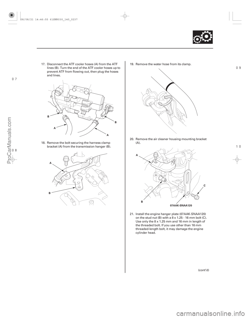
17. Disconnect the ATF cooler hoses (A) from the ATF lines (B). Turn the end of the ATF cooler hoses up to
prevent ATF from flowing out, then plug the hoses
and lines.
18. Remove the bolt securing the harness clamp bracket (A) from the transmission hanger (B). 19. Remove the water hose from its clamp.
20. Remove the air cleaner housing mounting bracket
(A).
21. Install the engine hanger plate (07AAK-SNAA120) onthestudnut(B)witha8x1.25-16mmbolt(C).
Useonlythe8x1.25mmand16mminlengthof
the threaded bolt. If you use other than 16 mm
threaded-length bolt, it may damage the engine
cylinder head.
(cont’d)
08/08/21 14:46:55 61SNR030_140_0237
ProCarManuals.com
DYNOMITE -2009-
Page 1225 of 2893
���
�(�#�'�������
���
���������
���������
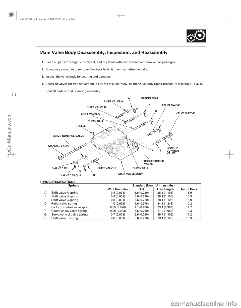
�"�����)���� SPRING SPECIFICATIONS Springs Standard (New)-Unit: mm (in.) Wire Diameter O.D. Free Length No. of Coils
14-303
Main Valve Body Disassembly, Inspection, and Reassembly
ASPRING SEAT
BC RELIEF VALVE
D VALVE SLEEVE
MAIN VALVE BODY CHECK BALLCOOLER CHECK
VALVEFE
LOCK-UP
CONTROL
VALVE
SHIFT VALVE E SHIFT VALVE A
SHIFT VALVE B
SHIFT VALVE C
CHECK BALL
ROLLER
SERVO CONTROL VALVE
MANUAL VALVE
VALVE CAP VALVE CAP CLIP G
H
1. Clean all parts thoroughly in solvent, and dry them with compressed air. Blow out all passages.
2. Do not use a magnet to remove the check balls, it may magnetize the balls.
3. Inspect the valve body for scoring and damage.
4. Check all valves for free movement. If any fail to slide freely, do the valve body repair procedure (see page 14-301).
5. Coat all parts with ATF during assembly.
A Shift valve A spring 0.8 (0.031) 5.6 (0.220) 28.1 (1.106) 15.9B Shift valve B spring 0.8 (0.031) 5.6 (0.220) 28.1 (1.106) 15.9
C Shift valve C spring 0.8 (0.031) 5.6 (0.220) 28.1 (1.106) 15.9
D Relief valve spring 1.0 (0.039) 9.6 (0.378) 34.1 (1.343) 10.2 E Lock-up control valve spring 0.65 (0.026) 7.1 (0.280) 23.1 (0.909) 12.7F Cooler check valve spring 0.85 (0.033) 6.6 (0.260) 27.0 (1.063) 11.3
G Servo control valve spring 0.7 (0.028) 6.6 (0.260) 35.7 (1.406) 17.2 H Shift valve E spring 0.8 (0.031) 5.6 (0.220) 28.1 (1.106) 15.9
08/08/21 14:51:13 61SNR030_140_0305
ProCarManuals.com
DYNOMITE -2009-
Page 1227 of 2893
����
�(�#�'�������
���
���������
���������
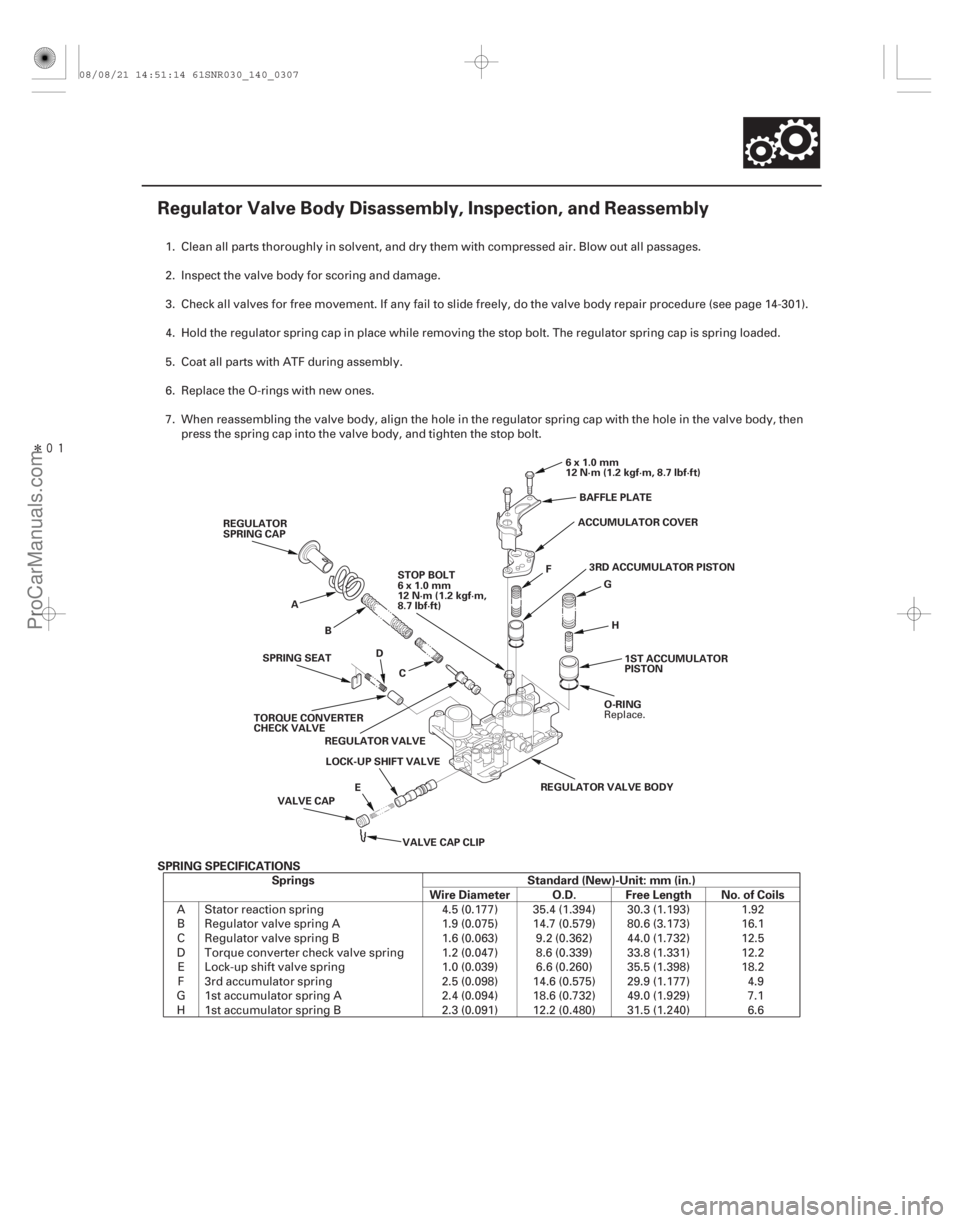
�"�����)���� SPRING SPECIFICATIONSSprings Standard (New)-Unit: mm (in.) Wire Diameter O.D. Free Length No. of Coils
14-305
Regulator Valve Body Disassembly, Inspection, and Reassembly
6x1.0mm
12 N·m (1.2 kgf·m, 8.7 lbf·ft)
F G
H 1ST ACCUMULATOR
PISTON
O-RING
REGULATOR VALVE BODY
LOCK-UP SHIFT VALVE
E
VALVE CAP CLIP
VALVE CAP REGULATOR VALVE
TORQUE CONVERTER
CHECK VALVE D
SPRING SEAT A
B
C ACCUMULATOR COVER
3RD ACCUMULATOR PISTON
REGULATOR
SPRING CAP
STOP BOLT
6x1.0mm
12 N·m (1.2 kgf·m,
8.7 lbf·ft) BAFFLE PLATE
1. Clean all parts thoroughly in solvent, and dry them with compressed air. Blow out all passages.
2. Inspect the valve body for scoring and damage.
3. Check all valves for free movement. If any fail to slide freely, do the valve body repair procedure (see page 14-301).
4. Hold the regulator spring cap in place while removing the stop bolt. The regulator spring cap is spring loaded.
5. Coat all parts with ATF during assembly.
6. Replace the O-rings with new ones.
7. When reassembling the valve body, align the hole in the regulator spring cap with the hole in the valve body, then
press the spring cap into the valve body, and tighten the stop bolt.
A Stator reaction spring 4.5 (0.177) 35.4 (1.394) 30.3 (1.193) 1.92 B Regulator valve spring A 1.9 (0.075) 14.7 (0.579) 80.6 (3.173) 16.1
C Regulator valve spring B 1.6 (0.063) 9.2 (0.362) 44.0 (1.732) 12.5
D Torque converter check valve spring 1.2 (0.047) 8.6 (0.339) 33.8 (1.331) 12.2 E Lock-up shift valve spring 1.0 (0.039) 6.6 (0.260) 35.5 (1.398) 18.2F 3rd accumulator spring 2.5 (0.098) 14.6 (0.575) 29.9 (1.177) 4.9
G 1st accumulator spring A 2.4 (0.094) 18.6 (0.732) 49.0 (1.929) 7.1 H 1st accumulator spring B 2.3 (0.091) 12.2 (0.480) 31.5 (1.240) 6.6
Replace.
08/08/21 14:51:14 61SNR030_140_0307
ProCarManuals.com
DYNOMITE -2009-
Page 1228 of 2893
���
�(�#�'�������
���
���������
���������
�"�����)���� SPRING SPECIFICATIONS Springs Standard (New)-Unit: mm (in.) Wire Diameter O.D. Free Length No. of Coils
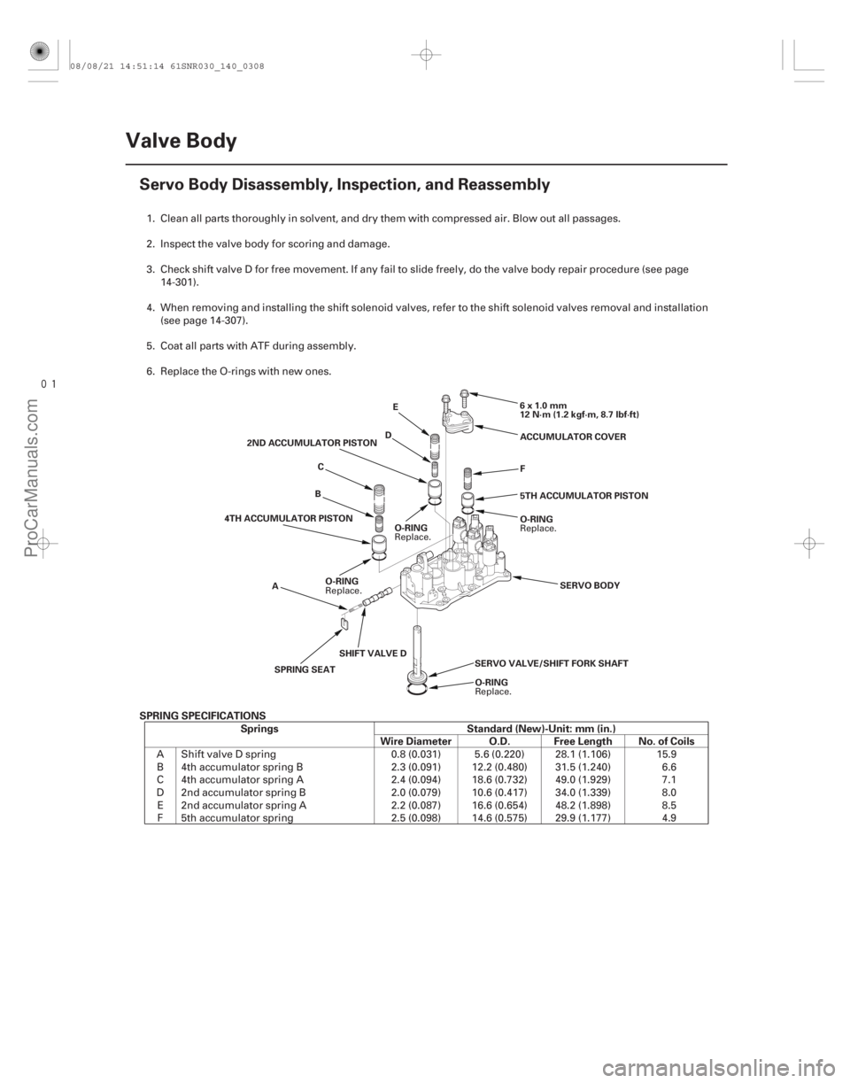
14-306Valve Body
Servo Body Disassembly, Inspection, and Reassembly
6x1.0mm
12 N·m (1.2 kgf·m, 8.7 lbf·ft)
O-RING
SERVO VALVE/SHIFT FORK SHAFT
SPRING SEAT ACCUMULATOR COVER
F
5TH ACCUMULATOR PISTON
SERVO BODY
O-RING
SHIFT VALVE D
A
O-RING
4TH ACCUMULATOR PISTON
O-RING
B
C
2ND ACCUMULATOR PISTON
DE
1. Clean all parts thoroughly in solvent, and dry them with compressed air. Blow out all passages.
2. Inspect the valve body for scoring and damage.
3. Check shift valve D for free movement. If any fail to slide freely, do the valve body repair procedure (see page
14-301).
4. When removing and installing the shift solenoid valves, refer to the shift solenoid valves removal and installation (see page 14-307).
5. Coat all parts with ATF during assembly.
6. Replace the O-rings with new ones.
A Shift valve D spring 0.8 (0.031) 5.6 (0.220) 28.1 (1.106) 15.9B 4th accumulator spring B 2.3 (0.091) 12.2 (0.480) 31.5 (1.240) 6.6
C 4th accumulator spring A 2.4 (0.094) 18.6 (0.732) 49.0 (1.929) 7.1
D 2nd accumulator spring B 2.0 (0.079) 10.6 (0.417) 34.0 (1.339) 8.0 E 2nd accumulator spring A 2.2 (0.087) 16.6 (0.654) 48.2 (1.898) 8.5F 5th accumulator spring 2.5 (0.098) 14.6 (0.575) 29.9 (1.177) 4.9
Replace.
Replace.
Replace.
Replace.
08/08/21 14:51:14 61SNR030_140_0308
ProCarManuals.com
DYNOMITE -2009-
Page 1303 of 2893
�µ�µ
�µ �µ
����
�����
�����
�����
�(�#�'�����������
��������������������� �����)����
K20Z2 engine model (left driveshaft only)
K20Z3 engine model
K20Z2 engine model
K20Z3 engine model
Model Left/Right Driveshaft Specified Length (A)
16-10Driveline/Axle
Dynamic Damper Replacement
A
A A
A
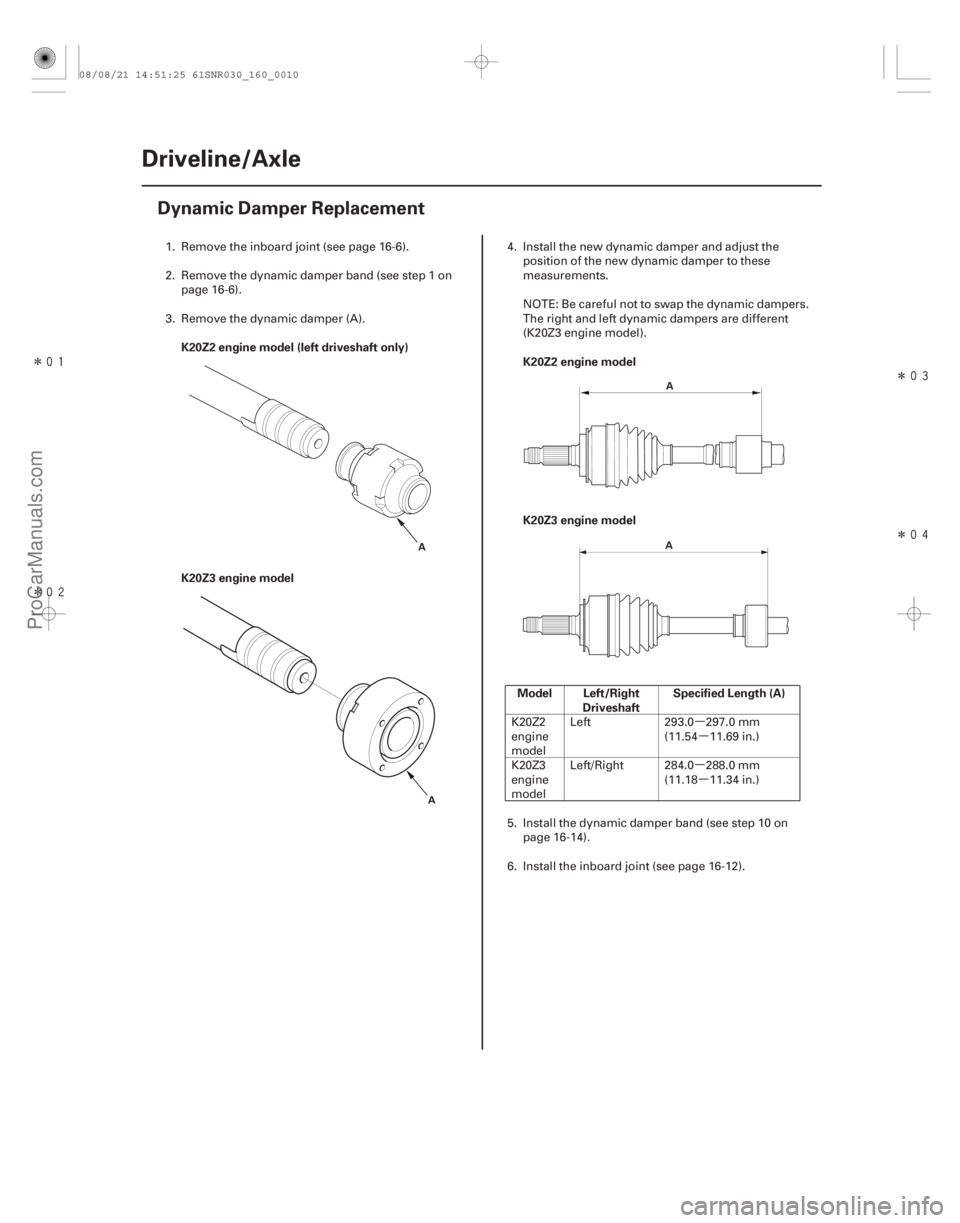
1. Remove the inboard joint (see page 16-6).
2. Remove the dynamic damper band (see step 1 on page 16-6).
3. Remove the dynamic damper (A). 4. Install the new dynamic damper and adjust the
position of the new dynamic damper to these
measurements.
NOTE: Be careful not to swap the dynamic dampers.
The right and left dynamic dampers are different
(K20Z3 engine model).
K20Z2
engine
model Left 293.0 297.0 mm
(11.54 11.69 in.)
K20Z3
engine
model Left/Right 284.0 288.0 mm
(11.18 11.34 in.)
5. Install the dynamic damper band (see step 10 on page 16-14).
6. Install the inboard joint (see page 16-12).
08/08/21 14:51:25 61SNR030_160_0010
ProCarManuals.com
DYNOMITE -2009-
Page 1307 of 2893
�µ�µ
�µ �µ
�µ �µ
�µ �µ �µ
�µ
�����
�����
����
����
Left driveshaft
Right driveshaft
Model Left/Right Driveshaft Specified Length (A)
16-14Driveline/Axle
Driveshaft Reassembly (cont’d)
A
A A
B C
A B
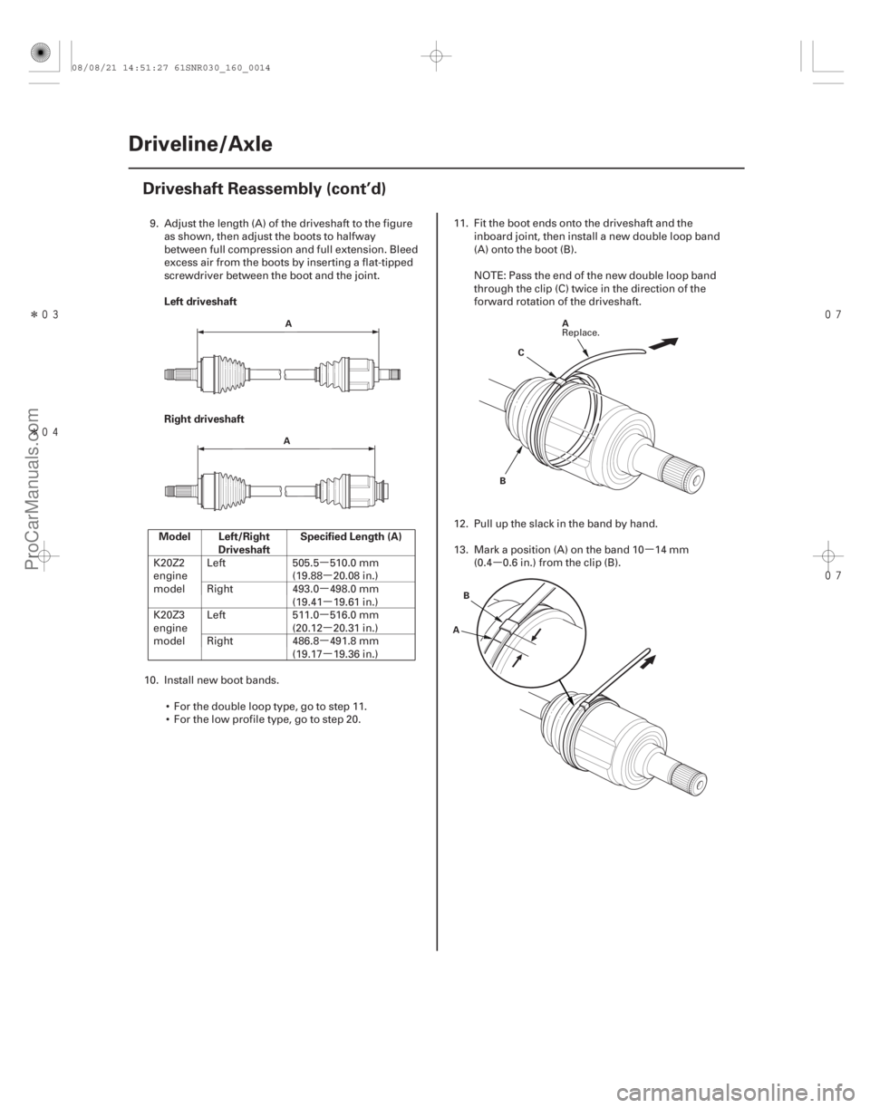
9. Adjust the length (A) of the driveshaft to the figure
as shown, then adjust the boots to halfway
between full compression and full extension. Bleed
excess air from the boots by inserting a flat-tipped
screwdriver between the boot and the joint.
K20Z2
engine
model Left 505.5 510.0 mm
(19.88 20.08 in.)
Right 493.0 498.0 mm (19.41 19.61 in.)
K20Z3
engine
model Left 511.0 516.0 mm
(20.12 20.31 in.)
Right 486.8 491.8 mm (19.17 19.36 in.)
10. Install new boot bands.
For the double loop type, go to step 11.
For the low profile type, go to step 20. 11. Fit the boot ends onto the driveshaft and the
inboard joint, then install a new double loop band
(A) onto the boot (B).
NOTE: Pass the end of the new double loop band
through the clip (C) twice in the direction of the
forward rotation of the driveshaft.
12. Pull up the slack in the band by hand.
13. Mark a position (A) on the band 10 14 mm (0.4 0.6 in.) from the clip (B).
Replace.
08/08/21 14:51:27 61SNR030_160_0014
ProCarManuals.com
DYNOMITE -2009-