Page 847 of 2893

C
B
A
6x1.0mm
12 N·m
(1.2 kgf·m,
8.7 lbf·ft)
A
7. Remove the roller (A), the select lock return sp")
���������
13-78Reverse Lockout System
Reverse Lockout Solenoid Disassembly/Reassembly (cont’d)
C
B
A
6x1.0mm
12 N·m
(1.2 kgf·m,
8.7 lbf·ft)
A
7. Remove the roller (A), the select lock return spring
(C), and select lock cam B.
8. Install the components of the r everse lockout
solenoid in the reverse order of removal.
9. Clean any dirt and oil from the mating surface of the reverse lockout solenoid and the change lever
assembly.
10. Apply liquid gasket, P/N 08718-0001 evenly to the change lever assembly mating surface of the
reverse lockout solenoid. Install the com ponent
within 5 minutes of applying the liquid gasket.
NOTE: If you apply liquid gasket P/N 08718-0012, the component must be installed within 4 minutes.
If too much time has passed after applying the liquid gasket, remove the old liquid gasket and
residue, then reapply new liquid gasket. 11. Install the reverse lockout solenoid (A).
12. Install the cable bracket and the shift cables (see
step 37 on page 13-97).
13. Connect the r everse lockout solenoid connector,
the back-up light switch connector, and the output
shaft (countershaft) speed sensor connector (see
step 39 on page 13-97).
14. Install the battery base (see step 41 on page 13-98).
15. Install the air cleaner assembly (see page 11-345).
16. Do the battery installation procedure (see page 22-69).
08/08/21 14:46:40 61SNR030_130_0080
ProCarManuals.com
DYNOMITE -2009-
Page 848 of 2893
���
13-79
Manual Transmission
Component Location Index
GEARSHIFT MECHANISM
TRANSMISSION FLUID BACK-UP LIGHT SWITCH
TRANSMISSION
CHANGE LEV")
����
������(�#�'���������������
�����
�����������������)���
13-79
Manual Transmission
Component Location Index
GEARSHIFT MECHANISM
TRANSMISSION FLUID BACK-UP LIGHT SWITCH
TRANSMISSION
CHANGE LEVER ASSEMBLY COUNTERSHAFT ASSEMBLY
MAINSHAFT ASSEMBLY
SYNCHRO RING and GEAR SHIFT FORK
COUNTERSHAFT
CHANGE LEVER
SYNCHRO SLEEVE and HUB
REVERSE SHIFT FORK
DIFFERENTIAL
REVERSE IDLER GEAR
MAINSHAFT Replacement, page 13-138
Inspection and Replacement, page 13-82 Test, page 13-83
Removal, page 13-84
Installation, page 13-91
Disassembly, page 13-99
Reassembly, page 13-133
Disassembly/Reassembly, page 13-105 Clearance Inspection, page 13-117
Clearance Inspection, page 13-108
Inspection, page 13-127 Clearance Inspection, page 13-106
Disassembly/Reassembly, page 13-107
Disassembly, page 13-119
Inspection, page 13-120
Reassembly, page 13-121
Bearing Replacement,page 13-130
Clearance Inspection,
page 13-104
Inspection and Reassembly,page 13-127
Clearance Inspection,
page 13-104
Disassembly, page 13-111
Inspection, page 13-112
Reassembly, page 13-113
Bearing and Oil Seal Replacement, page 13-129
Thrust Clearance Adjustment, page 13-131
08/08/21 14:47:17 61SNR030_130_0081
ProCarManuals.com
DYNOMITE -2009-
Page 869 of 2893

TRANSMISSION HOUSING
32 mm SEALING CAP
34 N·m (3.5 kgf·m, 25 lbf·ft)
10 mm SEALING WASHER")
�����
Exploded View - Transmission Housing
13-100Manual Transmission
Transmission Disassembly (cont’d)
TRANSMISSION HOUSING
32 mm SEALING CAP
34 N·m (3.5 kgf·m, 25 lbf·ft)
10 mm SEALING WASHER
FILLER PLUG
44 N·m (4.5 kgf·m, 33 lbf·ft)
40x56x8mmOILSEAL
10 mm FLANGE BOLT
44 N·m (4.5 kgf·m, 33 lbf·ft)
14 mm SEALING WASHER
TRANSMISSION HANGER A 8 mm FLANGE BOLT
27 N·m (2.8 kgf·m, 20 lbf·ft)
INTERLOCK BOLT
39 N·m (4.0 kgf·m, 29 lbf·ft)
OIL GUIDE PLATE M
72 mm SHIM
OIL GUTTER PLATE
DRAIN PLUG
39 N·m (4.0 kgf·m, 29 lbf·ft) 20 mm SEALING WASHER STEEL BALL SPRING
TRANSMISSION HANGER B DETENT BOLT
22 N·m (2.2 kgf·m, 16 lbf·ft)
12 mm SEALING WASHER
HARNESS BRACKET A
6 x 30 mm FLANGE BOLT
12 N·m (1.2 kgf·m, 9 lbf·ft) 8x14mmDOWELPIN
CHANGE LEVER ASSEMBLY TRANSMISSION HANGER
10 mm FLANGE BOLT
44 N·m (4.5 kgf·m, 33 lbf·ft)
6 x 20 mm FLANGE BOLT
12 N·m (1.2 kgf·m, 9 lbf·ft) 6 mm FLANGE BOLT
12 N·m (1.2 kgf·m, 9 lbf·ft) OUTPUT SHAFT (COUNTERSHAFT)
SPEED SENSOR
O-RING
80 mm SHIM Replace.
Replace.
Replace. Replace. Replace.Replace.
08/08/21 14:47:54 61SNR030_130_0102
ProCarManuals.com
DYNOMITE -2009-
Page 874 of 2893
����
13-105
Change Lever Assembly Disassembly/Reassembly
DUST COVEROIL SEAL
SHIFT ARM
COVER
SELECT STOP
PLATE DUST SEAL
INTERLOCK
5TH/6TH
SELECT
SP")
����
�(�#�'���������������
���������������
�"�����)����
13-105
Change Lever Assembly Disassembly/Reassembly
DUST COVEROIL SEAL
SHIFT ARM
COVER
SELECT STOP
PLATE DUST SEAL
INTERLOCK
5TH/6TH
SELECT
SPRING WASHER
REVERSE LOCKOUT
SOLENOID (MOLYBDENUM)
1ST/2ND
SELECT
SPRING
SELECT
LOCK CAM A
MBS RETURN
SPRING
CHANGE
LEVER COVER
SHIFT
ARM (MOLYBDENUM)
(MOLYBDENUM)
SELECT LEVER
SELECT
LOCK CAM B
ROLLER
CHANGE LEVER
6x1.0mm
12 N·m
(1.2 kgf·m,
8.7 lbf·ft)
8mm
SPRING
WASHER8mm
SPECIAL BOLT
31 N·m
(3.2 kgf·m,
23 lbf·ft)
MBS ARM
BREATHER CAP
NOTE:
Do not install components if too much time has passed after applying liquid gasket. Instead, remove the old residue, and reapply liquid gasket.
Prior to reassembling, clean all parts in solvent, dry them, and apply grease to the contact surfaces as shown.
Replace.
Replace.
Apply liquid gasket
(08C70-X0331S) to
the sealing surface. Be careful not to damage the dust seal
when installing it.
Turn toward the front of
the vehicle, and install it.
08/08/21 14:47:58 61SNR030_130_0107
ProCarManuals.com
DYNOMITE -2009-
Page 905 of 2893

13-136
Manual Transmission
Transmission Reassembly (cont’d)
Liquid gasket A
CB
6x1.0mm
12 N·m
(1.2 kgf·m,
8.7 lbf·ft) D
3")
�
��
�
�
�
��
Specified Torque:
8x1.25mm
27 N·m (2.8 kgf·m, 20 lbf·ft)
13-136
Manual Transmission
Transmission Reassembly (cont’d)
Liquid gasket A
CB
6x1.0mm
12 N·m
(1.2 kgf·m,
8.7 lbf·ft) D
39 N·m
(4.0 kgf·m,
29 lbf·ft)
B
14. Tighten the 8 mm flange bolts in a crisscross
pattern in several steps.
15. Clean any dirt or oil from the mating surface of the change lever assembly and the transmission
housing. Apply liquid gasket, P/N 08718-0001,
evenly to the mating surface of the change lever
assembly and the transmission housing. Install the
component within 5 minutes of applying the liquid
gasket.
NOTE: If you apply liquid gasket P/N 08718-0012, the component must be installed within 4 minutes.
If too much time has passed after applying the liquid gasket, remove the old liquid gasket and
residue, then reapply new liquid gasket. 16. Installthe8x14mmdowelpins(B)andthechange
lever assembly (C) with harness bracket A.
17. Apply liquid gasket, P/N 08718-0001, evenly to the threads of the inter lock bolt (D). Install the
component within 5 minutes of applying the liquid
gasket.
NOTE: If you apply liquid gasket P/N 08718-0012, the component must be installed within 4 minutes.
If too much time has passed after applying the liquid gasket, remove the old liquid gasket and
residue, then reapply new liquid gasket.
08/08/21 14:48:44 61SNR030_130_0138
ProCarManuals.com
DYNOMITE -2009-
Page 1148 of 2893
����
Automatic Transmission Fluid Capacity:
2.9 L (3.1 US qt) at change
6.5 L (6.9 US qt) at overhaul
14-232 Automatic Transmission
ATF R")
����
���� ����
�(�#�'�������
���
�����������
�������
� �����)����
Automatic Transmission Fluid Capacity:
2.9 L (3.1 US qt) at change
6.5 L (6.9 US qt) at overhaul
14-232 Automatic Transmission
ATF Replacement
A
18 x 1.5 mm
49 N·m
(5.0 kgf·m,
36 lbf·ft)
B
ATF
A
NOTE: Keep all foreign particles out of the transmission. 1. Park the vehicle on the level ground.
2. Warm up the engine to normal operating temperature (the radiator fan comes on), and turn
the engine off.
3. Remove the drain plug (A), and drain the automatic transmission fluid (ATF).
4. Reinstall the drain plug with a new sealing washer (B).
5. Refill the transmission with ATF into the dipstick hole to bring the fluid level between the upper
mark and the lower mark of the dipstick. Always
use Acura ATF-Z1 automatic transmission fluid
(ATF). Using a non-Acura ATF can affect shift
quality.
6. Check that the ATF level is between the upper mark
and the lower mark of the dipstick.
7. Insert the dipstick back into the transmission with the letters ‘‘ATF’’ pointing toward the front of the
vehicle. 8. If the maintenance minder required to replace the
ATF, reset the maintenance minder (see page 3-4),
and this procedure is complete. If the maintenance
minder did not require you to replace the ATF, go
to step 9.
9. Connect the HDS to the DLC (A) located under the driver’s side of the dashboard.
10. Turn the ignition switch to ON (II). Make sure the HDS communicates with the PCM. If it does not, go
to the DLC circuit troubleshooting (see page
11-204).
11. Select BODY ELECTRICAL with the HDS.
12. Select ADJUSTMENT in the GAUGES MENU with the HDS.
13. Select RESET in the MAINTENANCE MINDER MENU with the HDS.
14. Select RESETTING THE ATF with the HDS.
NOTE: If you changed the engine oil at the same
time with the ATF, select RESETTING THE ENGINE
OIL LIFE AND ATF with the HDS instead.
Replace.
08/08/21 14:46:53 61SNR030_140_0234
ProCarManuals.com
DYNOMITE -2009-
Page 1260 of 2893
����
���� ����
����
14-336Shafts and Clutches
1st, 2nd, and 3rd Clutch Reassembly (cont’d)
07LAE-PX40000
AB
C A
B
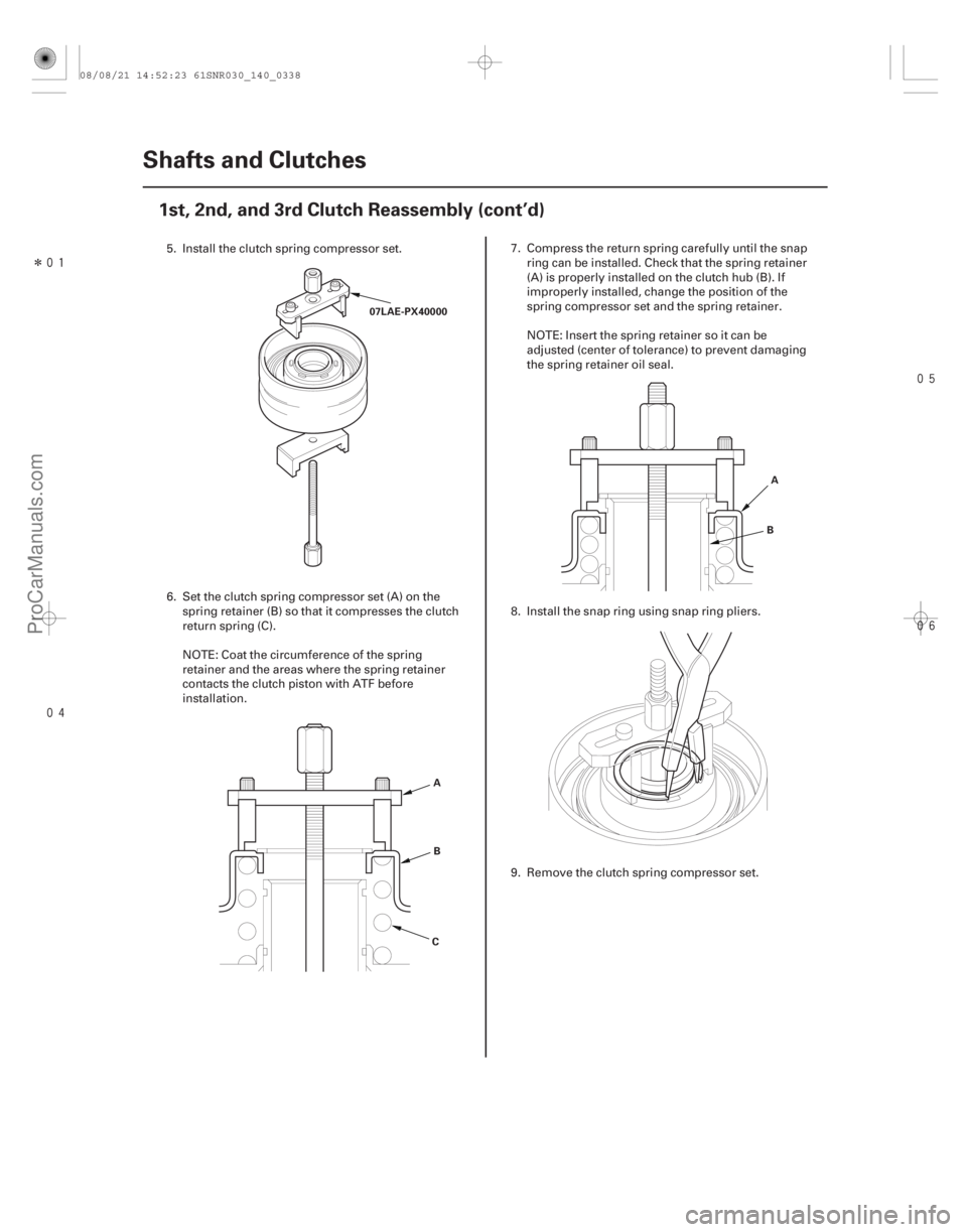
5. Install the clutch spring compressor set.
6. Set the clutch spring compressor set (A) on the spring retainer (B) so that it compresses the clutch
return spring (C).
NOTE: Coat the circumference of the spring
retainer and the areas where the spring retainer
contacts the clutch piston with ATF before
installation. 7. Compress the return spring carefully until the snap
ring can be installed. Check that the spring retainer
(A) is properly installed on the clutch hub (B). If
improperly installed, change the position of the
spring compressor set and the spring retainer.
NOTE: Insert the spring retainer so it can be
adjusted (center of tolerance) to prevent damaging
the spring retainer oil seal.
8. Install the snap ring using snap ring pliers.
9. Remove the clutch spring compressor set.
08/08/21 14:52:23 61SNR030_140_0338
ProCarManuals.com
DYNOMITE -2009-
Page 1352 of 2893
�����
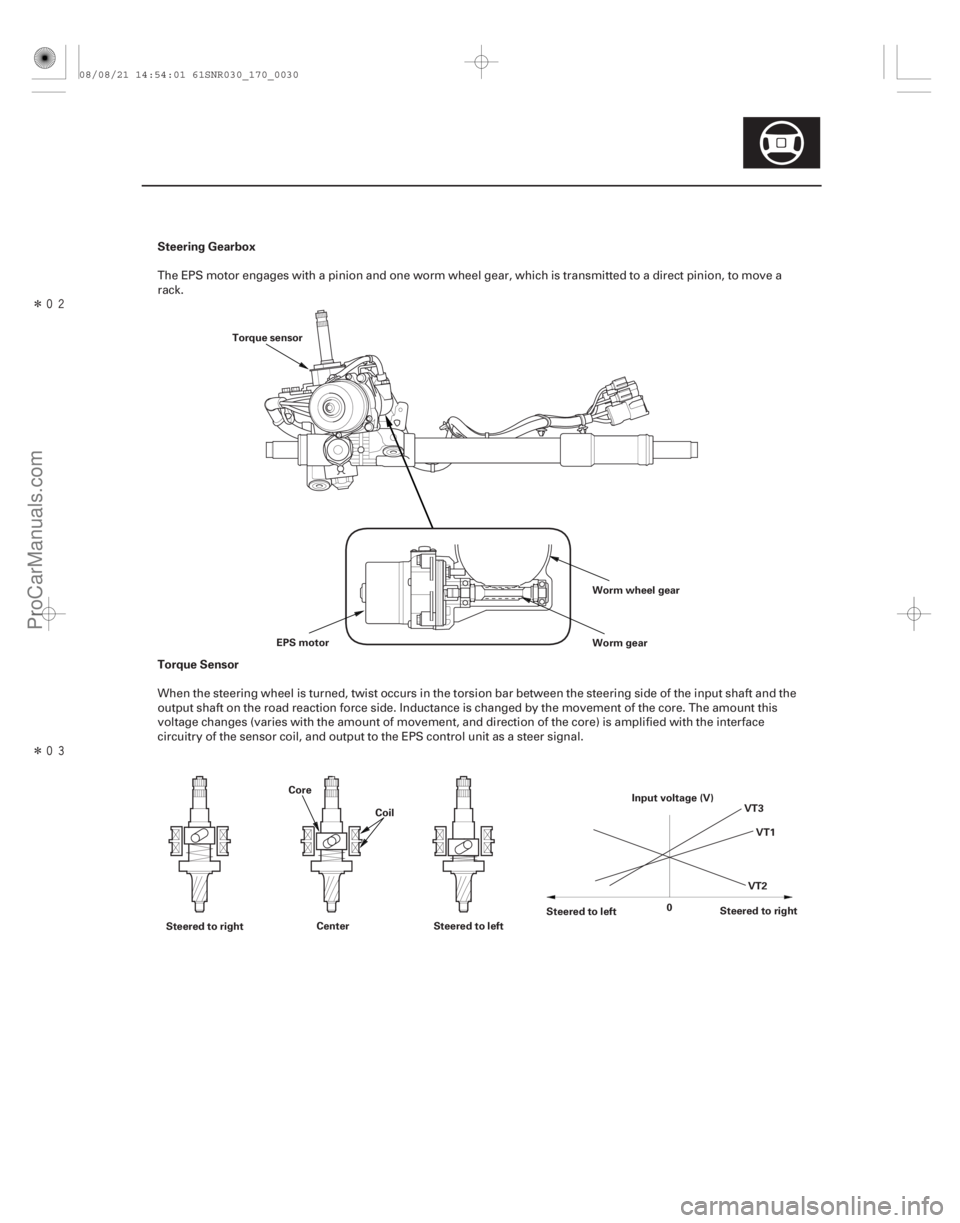
�����Steering Gearbox
Torque Sensor
17-29
Worm wheel gear
Worm gear
EPS motor
Torque sensor
Steered to right Center Steered to left Steered to left
Steered to right
0 VT1
VT3
VT2
Input voltage (V)
Core
Coil
The EPS motor engages with a pinion and one worm wheel gear, which is transmitted to a direct pinion, to move a
rack.
When the steering wheel is turned, twist occurs in the torsion bar between the steering side of the input shaft and the
output shaft on the road reaction force side. Inductance is changed by the movement of the core. The amount this
voltage changes (varies with the amount of movement, and direction of the core) is amplified with the interface
circuitry of the sensor coil, and output to the EPS control unit as a steer signal.
08/08/21 14:54:01 61SNR030_170_0030
ProCarManuals.com
DYNOMITE -2009-