���
�(�#�'���������������
�
�������
�����
� �����)���
����
�(�#�'���������������
�
�����
���������������)����
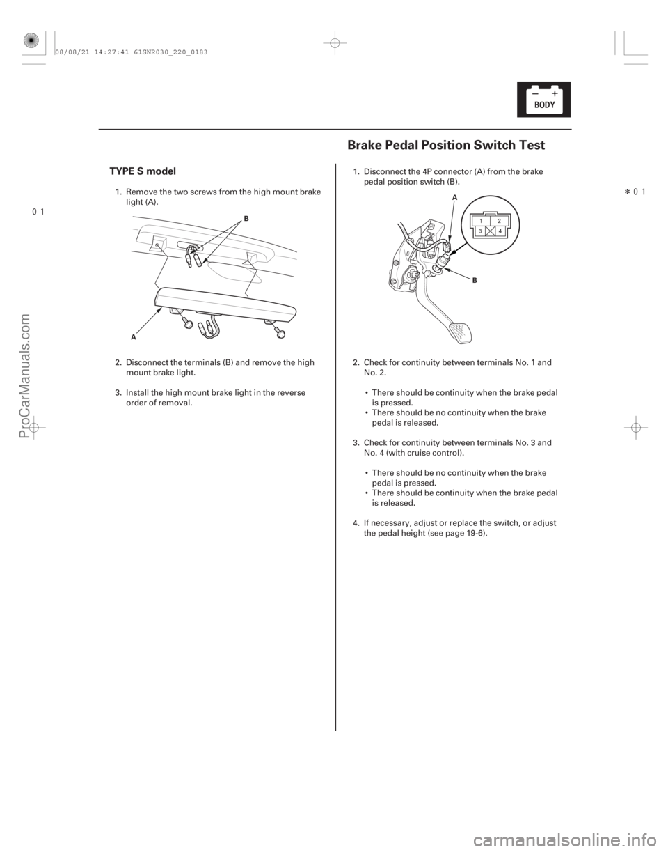
TYPE S model
22-18122-181
Brake Pedal Position Switch Test
A B
A
B
1. Remove the two screws from the high mount brakelight (A).
2. Disconnect the terminals (B) and remove the high mount brake light.
3. Install the high mount brake light in the r everse
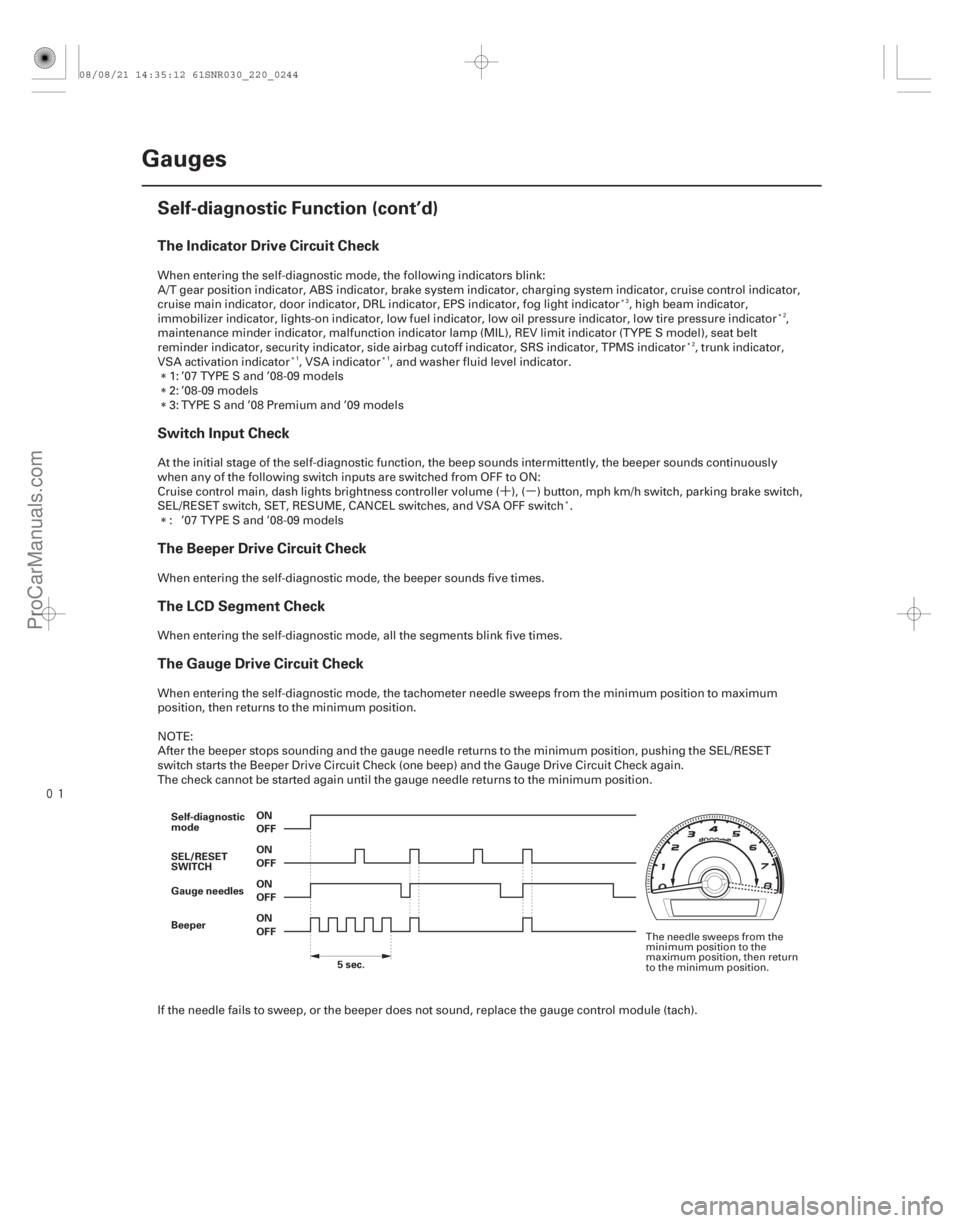
order of removal. 1. Disconnect the 4P connector (A) from the brake
pedal position switch (B).
2. Check for continuity between terminals No. 1 and No. 2.
There should be continuity when the brake pedal is pressed.
There should be no continuity when the brake pedal is released.
3. Check for continuity between terminals No. 3 and No. 4 (with cruise control).
There should be no continuity when the brake pedal is pressed.
There should be continuity when the brake pedal is released.
4. If necessary, adjust or replace the switch, or adjust the pedal height (see page 19-6).
08/08/21 14:27:41 61SNR030_220_0183
ProCarManuals.com
DYNOMITE -2009-
���
�(�#�'���������������
�
�������
�����
� �����)���
����
�(�#�'���������������
�
�����
���������������)����
TYPE S model
22-18122-181
Brake Pedal Position Switch Test
A B
A
B
1. Remove the two screws from the high mount brakelight (A).
2. Disconnect the terminals (B) and remove the high mount brake light.
3. Install the high mount brake light in the r everse
order of removal. 1. Disconnect the 4P connector (A) from the brake
pedal position switch (B).
2. Check for continuity between terminals No. 1 and No. 2.
There should be continuity when the brake pedal is pressed.
There should be no continuity when the brake pedal is released.
3. Check for continuity between terminals No. 3 and No. 4 (with cruise control).
There should be no continuity when the brake pedal is pressed.
There should be continuity when the brake pedal is released.
4. If necessary, adjust or replace the switch, or adjust the pedal height (see page 19-6).
08/08/21 14:27:41 61SNR030_220_0183
ProCarManuals.com
DYNOMITE -2009-
�´�µ
���
The Indicator Drive Circuit Check
Switch Input Check
The Beeper Drive Circuit Check
The LCD Segment Check
The Gauge Drive Circuit Check
22-242Gauges
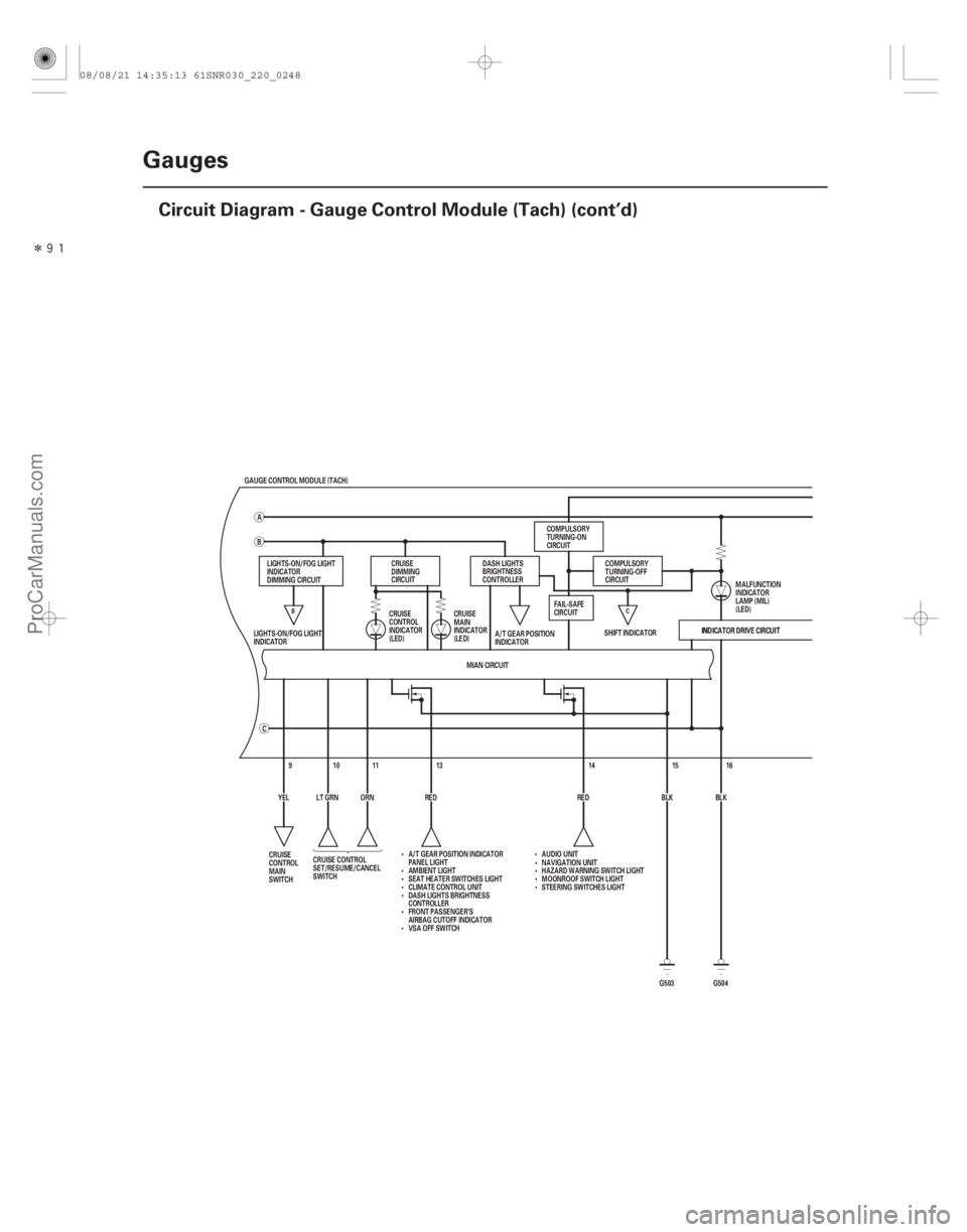
Self-diagnostic Function (cont’d)
OFF ON
OFF ON
OFF ON
OFF ON
Gauge needles
Beeper
5sec.
Self-diagnostic
mode
SEL/RESET
SWITCH
When entering the self-diagnostic mode, the following indicators blink:
A/T gear position indicator, ABS indicator, brake system indicator, charging system indicator, cruise control indicator,
cruise main indicator, door indicator, DRL indicator, EPS indicator, fog light indicator , high beam indicator,
immobilizer indicator, lights-on indicator, low fuel indicator, low oil pressure indicator, low tire pressure indicator ,
maintenance minder indicator, malfunction indicator lamp (MIL), REV limit indicator (TYPE S model), seat belt
reminder indicator, security indicator, side airbag cutoff indicator, SRS indicator, TPMS indicator , trunk indicator,
VSA activation indicator , VSA indicator , and washer fluid level indicator.
1: ’07 TYPE S and ’08-09 models
2: ’08-09 models
3: TYPE S and ’08 Premium and ’09 models
At the initial stage of the self-diagnostic function, the beep sounds intermittently, the beeper sounds continuously
when any of the following switch inputs are switched from OFF to ON:
Cruise control main, dash lights brightness controller volume ( ), ( ) button, mph km/h switch, parking brake switch,
SEL/RESET switch, SET, RESUME, CANCEL switches, and VSA OFF switch . : ’07 TYPE S and ’08-09 models
When entering the self-diagnostic mode, the beeper sounds five times.
When entering the self-diagnostic mode, all the segments blink five times.
When entering the self-diagnostic mode, the tachometer needle sweeps from the minimum position to maximum
position, then returns to the minimum position.
NOTE:
After the beeper stops sounding and the gauge needle returns to the minimum position, pushing the SEL/RESET
switch starts the Beeper Drive Circuit Check (one beep) and the Gauge Drive Circuit Check again.
The check cannot be started again until the gauge needle returns to the minimum position.
If the needle fails to sweep, or the beeper does not sound, replace the gauge control module (tach).
3 2
2
11
The needle sweeps from the
minimum position to the
maximum position, then return
to the minimum position.
08/08/21 14:35:12 61SNR030_220_0244
ProCarManuals.com
DYNOMITE -2009-