Page 2011 of 2893
�
��
Special Tools Required
Removal
Installation
22-65
Under-hood Fuse/Relay Box
Removal and Installation
A
B
Relay puller 07AAC-000A1A01. Do the b")
����
�(�#�'���������������������������
����� �����)�
��
Special Tools Required
Removal
Installation
22-65
Under-hood Fuse/Relay Box
Removal and Installation
A
B
Relay puller 07AAC-000A1A01. Do the battery terminal disconnection procedure (see page 22-68).
2. Remove the screws (A) for the alternator and battery cable terminals from the under-hood fuse/
relay box.
3. Remove the bottom cover (B) from the under-hood fuse/relay box.
4. Disconnect the connectors from the under-hood fuse/relay box.
5. Carefully remove the relays using the relay puller. NOTE: Do not use pliers. Pliers will damage the
relays, which could cause the engine to stall or not
start. 1. Install the relays and connect the connectors to the
under-hood fuse/relay box, then install the under-
hood fuse/relay box in the r everse order of removal.
2. Install the removed parts in the reverse order of removal.
3. Do the battery terminal reconnection procedure (see page 22-68).
4. Confirm that all systems work properly.
08/08/21 14:24:03 61SNR030_220_0067
ProCarManuals.com
DYNOMITE -2009-
Page 2012 of 2893
����
Special Tools Required
Removal
Installation
22-66Under-dash Fuse/Relay Box
Removal and Installation
A
Relay puller 07AAC-000A1A0
SRS components a")
���
�(�#�'�������������������������������
� �����)����
Special Tools Required
Removal
Installation
22-66Under-dash Fuse/Relay Box
Removal and Installation
A
Relay puller 07AAC-000A1A0
SRS components are located in this area. Review the
SRS component locations (see page 24-11), and
precautions and procedures (see page 24-13) before
doing repairs or serving.
1. Do the battery terminal disconnection procedure (see page 22-68).
2. Remove the driver’s dashboard lower cover (see page 20-102).
3. Disconnect the connectors from the fuse side of the under-dash fuse/relay box (A).
4. Remove the mounting bolt, and pull the fuse/relay box away from the body.
5. Disconnect the connectors from the back side of the under-dash fuse/relay box, then remove the under-
dash fuse/relay box.
6. Carefully remove the relays using the relay puller. NOTE: Do not use pliers. Pliers will damage the
relays, which could cause the engine to stall or not
start. 1. Install the relays and connect the connectors to the
under-dash fuse/relay box, then install the under-
dash fuse/relay box in the reverse order of removal.
2. Install the removed parts in the reverse order of removal.
3. Do the battery terminal reconnection procedure (see page 22-68).
4. Register the immobilizer system with the HDS (see page 22-329).
NOTE: The imoes unit is built into the MICU which
is part of the under-dash fuse/relay box. Because of
this construction, the imoes must be registered, or
the vehicle will not start.
5. Confirm that all systems work properly.
08/08/21 14:24:04 61SNR030_220_0068
ProCarManuals.com
DYNOMITE -2009-
Page 2016 of 2893
����
Special Tools Required
Relay Test
Normally-open type
22-70Relays
Power Relay Test
07AAC-000A1A0
31
42
3 42
1
Relay puller 07AAC-000A")
����
���
����
�(�#�'���������������������������
���
�������)����
Special Tools Required
Relay Test
Normally-open type
22-70Relays
Power Relay Test
07AAC-000A1A0
31
42
3 42
1
Relay puller 07AAC-000A1A0
Use this chart to identify the type of relay, then do the
test listed for it. Carefully remove the relays using the
relay puller. Do not use pliers. Pliers will damage the
relay.
A/C compressor clutch relay Normally- open type
A/C condenser fan relay
Blower motor relay
Console accessory power socket
relay
Electronic throttle control system
(ETCS) control relay
Fog light relay
Front accessory power socket
relay
Ignition coil relay
PGM-FI main relay 1 (FI MAIN)
PGM-FI main relay 2 (FUEL PUMP)
PGM-FI subrelay
Power window relay
Radiator fan relay
Rear window defogger relay
Seat heater relay (HIGH)
Starter cut relay
Fan control relay Five-terminal
type
Power mirror defogger relay
Seat heater relay (LOW)
: TYPE S and ’08 PREMIUM and ’09 models Check for continuity between the terminals.
There should be continuity between terminals No. 1 and No. 2 when the battery positive terminal is
connected to terminal No. 4, and the battery negative
terminal is connected to terminal No. 3.
There should be no continuity between terminals No. 1 and No. 2 when power is disconnected.
08/08/21 14:24:05 61SNR030_220_0072
ProCarManuals.com
DYNOMITE -2009-
Page 2019 of 2893
����
�(�#�'���������������������������������������)�
��
22-73
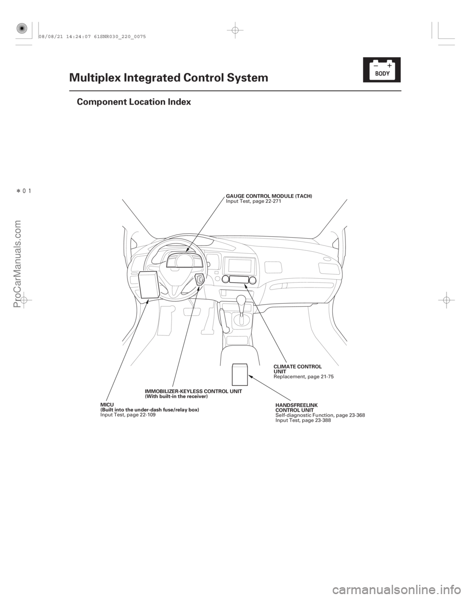
Multiplex Integrated Control System
Component Location Index
GAUGE CONTROL MODULE (TACH)
IMMOBILIZER-KEYLESS CONTROL UNIT
(With built-in the receiver)
MICU
(Built into the under-dash fuse/relay box) CLIMATE CONTROL
UNIT
HANDSFREELINK
CONTROL UNIT
Input Test, page 22-271
Input Test, page 22-109 Replacement, page 21-75
Self-diagnostic Function, page 23-368
Input Test, page 23-388
08/08/21 14:24:07 61SNR030_220_0075
ProCarManuals.com
DYNOMITE -2009-
Page 2026 of 2893
�
��
�µ�µ
�µ
Body Controller Area Network (B-CAN) and Fast Controller Area Network (F-CAN)
22-80 Multiplex Integrated Control System
System Desc")
����
�(�#�'���������������������������������������)�
��
�µ�µ
�µ
Body Controller Area Network (B-CAN) and Fast Controller Area Network (F-CAN)
22-80 Multiplex Integrated Control System
System Description
GAUGE CONTROL MODULE (TACH)
CAN H CAN L
MICU
ECM/PCM
(F-CAN)
(B-CAN)UNDER-DASH FUSE/RELAY BOX
DATA LINK CONNECTOR
SRS UNIT
ABS MODULATOR-CONTROL UNIT*1
VSA MODULATOR-CONTROL UNIT*2
YAW RATE-LATERAL
ACCELERATION SENSOR*2
EPS CONTROL UNIT
TPMS CONTROL UNIT*3
F-CAN
TRANSCEIVER
B-CAN
TRANSCEIVER
IMMOBILIZER-
KEYLESS CONTROL
UNITCLIMATE
CONTROL
UNIT
HANDSFREELINK
CONTROL UNIT*4
*1: ’06 07 Touring and Premium models
*2: ’07 TYPE S and ’08 09 models
*3: ’08 09 models
*4: ’09 model with navigation system
The body controller area network (B-CAN) and the fast controller area network (F-CAN) share information between
multiple electronic control units (ECUs). B-CAN communication moves at a slower speed (33.33 kbps) for convenience
related items and for other functions. F-CAN information moves at a faster speed (500 kbps) for ‘‘real time’’ functions
such as fuel and emissions data. To allow both systems to share information, the gauge control module translates
information from B-CAN to F-CAN and from F-CAN to B-CAN.
The single wire method is used between the units not requiring the communication to move at a fast speed.
Using a single wire method reduces the number of the wires used on the body controller area network.
08/08/21 14:24:08 61SNR030_220_0082
ProCarManuals.com
DYNOMITE -2009-
Page 2028 of 2893

The MICU (built into the under-dash fuse/relay box) is one of the B-CAN components. T")
MICU Control Functions Index
SystemFunction
22-82Multiplex Integrated Control System
System Description (cont’d)
The MICU (built into the under-dash fuse/relay box) is one of the B-CAN components. The MICU controls many
systems related to the body controller area and security system, and also works as a gateway to the diagnose the
other B-CAN connected ECUs with the HDS.
Refer to the each system circuit diagram in detail.
Multiplex Control Sends the switch input signal information to the MICU and outputs the information. The MICU controls the ECUs electric load and communication based upon the information
received the B-CAN.
On-Board Diagnosis The MICU has a gateway function which sends the results of the MICU internal diagnosis and the B-CAN connected ECUs diagnosis to the HDS.
Self-Diagnosis Test mode 1 diagnoses the communication line between the MICU and B-CAN connected unit. Test mode 2 checks the switch inputs connected to the MICU.
Interior Light(s) The MICU controls the interior lights ON, OFF and dimming based upon the information of the related switches and/or the B-CAN related information.
Sleep Function The MICU has a sleep function, which it enters during the power down mode.
The MICU also controls the function of these circuits: Entry lights control (map lights and ceiling light)
Exterior lights control (including the daytime running lights control)
Horn
Interlock system
Key-in reminder
Keyless entry
Lights-on reminder
Power door locks
Power window key-off timer
Seat belt reminder
Security alarm
Turn signal/hazard flasher
Wiper/washer
08/08/21 14:24:08 61SNR030_220_0084
ProCarManuals.com
DYNOMITE -2009-
Page 2029 of 2893

F-CAN (500 kbps)
SRS UNIT MICU
ECM/PCM
ABS MODULATOR-
CONTROL UNIT* IMMOBILIZER-
KEYLESS
CONTROL UNIT
K")
�����
Self-diagnostic Function
22-83
GAUGE CONTROL MODULE
CAN H CAN L B-CAN
B-CAN (33.33 kbps)
F-CAN (500 kbps)
SRS UNIT MICU
ECM/PCM
ABS MODULATOR-
CONTROL UNIT* IMMOBILIZER-
KEYLESS
CONTROL UNIT
K-LINE
DATA LINK
CONNECTOR HDS CLIMATE CONTROL
UNIT
TMPS CONTROL
UNIT* EPS CONTROL
UNIT
NAVIGATION
UNIT
VSA MODULATOR-
CONTROL UNIT*
HANDSFREELINK
CONTROL UNIT*
AUDIO UNIT
YAWRATE-LATERAL
ACCELERATION
SENSOR*
*1: ’06-08 Touring and Premium models
*2: ’07 TYPES and ’08-09 models
*3: ’08-09 models
*4: ’09 model with navigation system
1
3 2
4
2
By connecting the HDS to the data link connector (DLC), the HDS can retrieve the diagnostic results from the MICU via
a diagnostic line called K-LINE. The K-LINE is distinguished from the CAN line, and connected to the CAN related ECUs.
The MICU is a gateway between the HDS and B-CAN related ECUs, and sends B-CAN diagnostic results to the HDS.
When doing a function test with the HDS, the HDS sends an output signal through the K-LINE to the MICU. The MICU
either relays the request to another ECU, or commands the function its self.
(cont’d)
08/08/21 14:24:09 61SNR030_220_0085
ProCarManuals.com
DYNOMITE -2009-
Page 2031 of 2893

Daytime Running")
Power Supply Voltage Monitoring Function
Entry Lights Control System
Lighting System (Headlights, Parking Lights, Fog Lights, Side Marker Lights, License Plate
Lights, and Taillights)
Daytime Running Lights
Turn Signal/Hazard Warning Lights
Door Lock Response Operation
Power Window Key-off Operation
InputOutput
Input Output
Input Output
Input Output
Input Output
Input Output
Input Output
22-85
The MICU monitors the power supply voltage (back-up voltage). If the voltage goes below 10 V, the MICU sends a MICU message and will not
store DTCs.
MICU Battery voltage MICU : MICU internal circuit
The MICU controls the ceiling light ON/OFF and dimming based upon input signals from each switch. MICU IG1 power supply Ignition key switch
Driver’s door switch
Front passenger’s door switch
Left rear door switch
Right rear door switch
Driver’s door lock knob switch (LOCK) Interior light
B-CAN Keyless LOCK signal
The MICU contains the relay circuits for the headlight high/low beams and taillights, and controls the lighting system ON/OFF based upon input
signals from the combination light switch. MICU Headlight OFF switch Headlight ON switch
Fog light switch
Dimmer switch
Combination light switch (parking lights, side marker lights,
license plate lights, and taillights)
Passing switch Headlights (low beam)
Headlights (high beam)
Parking lights
Fog lights
Side marker lights
License plate lights
Taillights
The MICU controls the exterior lights as a daytime running lights based upon input signals from each switch. MICU Headlight OFF switch Headlight ON switch
Dimmer switch
Combination light switch (parking lights, side marker lights,
license plate lights, and taillights)
Passing switch Headlights (low beam)
Headlights (high beam)
Parking lights
Slide marker lights
License plate lights
Taillights
B-CAN Transmission range switch (P position)
The MICU controls the turn signal/hazard warning lights based upon input signals from the turn signal and hazard warning switches. MICU IG1 power supply Turn signal switch (left/right)
Hazard warning switch Turn signal lights (left/right)
The MICU controls the door lock actuators based upon B-CAN signals. B-CAN Door lock signals Door lock actuator (LOCK/UNLOCK) Driver’s door lock actuator (UNLOCK)
Trunk lid release actuator
The MICU controls the power windows key-off operation based upon input signals from each switch. MICU IG1 power supply Ignition key switch
Driver’s door switch
Front passenger’s door switch Power window key-off timer
(cont’d)
08/08/21 14:24:09 61SNR030_220_0087
ProCarManuals.com
DYNOMITE -2009-