����
���
����
�(�#�'���������������������������
���
�������)����
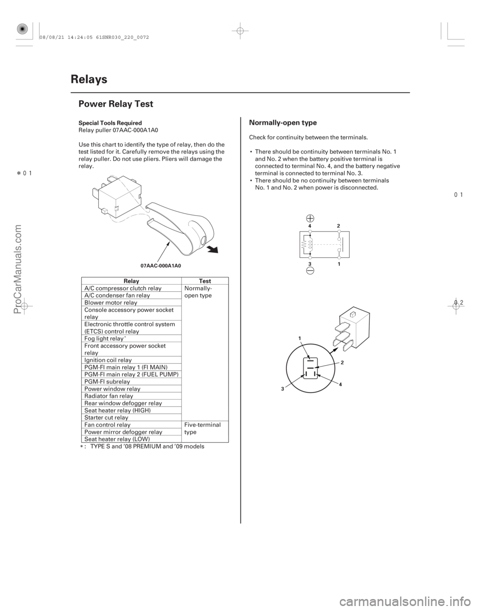
Special Tools Required
Relay Test
Normally-open type
22-70Relays
Power Relay Test
07AAC-000A1A0
31
42
3 42
1
Relay puller 07AAC-000A1A0
Use this chart to identify the type of relay, then do the
test listed for it. Carefully remove the relays using the
relay puller. Do not use pliers. Pliers will damage the
relay.
A/C compressor clutch relay Normally- open type
A/C condenser fan relay
Blower motor relay
Console accessory power socket
relay
Electronic throttle control system
(ETCS) control relay
Fog light relay
Front accessory power socket
relay
Ignition coil relay
PGM-FI main relay 1 (FI MAIN)
PGM-FI main relay 2 (FUEL PUMP)
PGM-FI subrelay
Power window relay
Radiator fan relay
Rear window defogger relay
Seat heater relay (HIGH)
Starter cut relay
Fan control relay Five-terminal
type
Power mirror defogger relay
Seat heater relay (LOW)
: TYPE S and ’08 PREMIUM and ’09 models Check for continuity between the terminals.
There should be continuity between terminals No. 1 and No. 2 when the battery positive terminal is
connected to terminal No. 4, and the battery negative
terminal is connected to terminal No. 3.
There should be no continuity between terminals No. 1 and No. 2 when power is disconnected.
08/08/21 14:24:05 61SNR030_220_0072
ProCarManuals.com
DYNOMITE -2009-
�µ�µ�µ
�(�#�'���������������������
���������
�������)����
Description
Outside Air Temperature Indicator Logic Update to the outside air temperature
indicator while driving
Troubleshooting
22-279
Outside Air Temperature Indicator Calibration
The outside temperature sensor is located behind the
center of the front bumper. The gauge control module
(tach) uses measurements from this sensor to display
the outside air temperature.
Because of the location of the sensor, it may be affected
by heat reflection from the road, engine and radiator
heat or hot exhaust from surrounding traffic.
These conditions can heat soak the outside air
temperature sensor and cause inaccurate readings.
Logic has been written into the gauge control module
(tach) to help prevent abnormal or fluctuating outside
air temperature indicator readings.
Initial outside air temperature indication after the
ignition switch is turned to ON (II).
If the engine coolant temperature is 60 °C (140 °F) or higher when the ignition switch is turned to ON (II),
the outside air temperature indicated the last time the
key was turned off will be displayed regardless of the
current temperature measured by the outside air
temperature sensor.
If the engine coolant temperature is 59 °C (139 °F) or lower when the ignition switch is turned to ON (II), the
current temperature measured by the outside air
temperature sensor will be indicated. If the temperature measured by the outside air
temperature sensor is greater than the temperature on
the outside air temperature indicator, the outside air
temperature indicator will increase by 1 °C (1.8 °F) per
minute after the vehicle speed is greater than 30 km/h
(19 mph) for more than 1 minute and 30 seconds. It will
continue to increase until the current outside air
temperature is indicated. So, the first change to the
outside air temperature indicator is 1 minute and
30 seconds after the vehicle speed is greater than
30 km/h (19 mph). If the vehicle speed drops below
30 km/h (19 mph), the indicator will not update again
until the vehicle speed is increased to 30 km/h (19 mph)
or more for more than 1 minute and 30 seconds again.
If the outside air temperature is less than the indicated
temperature, the temperature will decrease 1 °C every
2 seconds (1 °F
every 1.1 seconds) until the current
outside air temperature is indicated regardless of
vehicle speed.
If the indicator displays ‘‘ ’’ for more than 2
seconds after selecting the outside air temperature
display mode, check the outside air temperature sensor
(see page 21-68), or gauge control module self-
diagnosis (see page 22-241).
(cont’d)
08/08/21 14:36:00 61SNR030_220_0281
ProCarManuals.com
DYNOMITE -2009-