Page 1598 of 2893
����
VSA Modulator-Control Unit Inputs and Outputs for 37P Connector (Connector Disconnected)
TerminalnumberWir")
�•�•�•
�•�•�•
�´
�´
�´
���
�(�#�'���������������
�����������������������)����
VSA Modulator-Control Unit Inputs and Outputs for 37P Connector (Connector Disconnected)
TerminalnumberWire color Terminal sign Description Signal
19-106VSA System Components
System Description
NOTE: Standard battery voltage is about 12 V.
1 RED CAN-L F-CAN communication circuit
3 BLU STR-D Detects steering angle sensor signal
6 PNK FR-GND Detects right-front wheel speed sensor signal
7 ORN SVCC Power source for the steering angle sensor With ignition switch ON (II): about 5.0 V
8 PUR RL-GND Detects left-rear wheel speed sensor signal
9 LT GRN RR B Detects right-rear wheel speed sensor signal
10 BRN SGND Ground for the steering angle sensor
11 RED FL-GND Detects left-front wheel speed sensor signal
13 WHT FSR B Power source for the fail-safe relay Battery voltage at all times
14 RED MR B Power source for the motor relay Battery voltage at all times
Wire side of female terminals
08/08/21 15:04:53 61SNR030_190_0106
ProCarManuals.com
DYNOMITE -2009-
Page 1606 of 2893
������(�#�'���������������
�����������������������)����
�´ �´
19-114VSA System Components
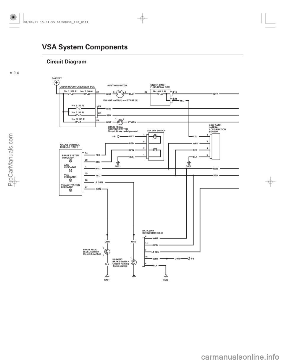
Circuit Diagram
UNDER-DASH
FUSE/RELAY BOX
No. 4 (7.5 A)
IGNITION SWITCH
IG1 HOT in ON (II) and START (III)
BRAKE PEDAL
POSITION SWITCH
Closed: Brake pedal pressed 1
2
WHTRED
YAW RATE-
LATERAL
ACCELERATION
SENSOR
WHT RED 1
3
4
YEL
5
BLK
4
2
1 VSA OFF SWITCH
WHT
WHT
RED
5
No. 3 (40 A)
No.1(100A) No.2(50A)
No. 3 (30 A)
No. 12 (15 A)
UNDER-HOOD FUSE/RELAY BOX
BATTERY
ABS
INDICATOR
BRAKE SYSTEM
INDICATOR
1
VSA ACTIVATION
INDICATOR VSA
INDICATOR
19
28
27
GAUGE CONTROL
MODULE (TACH)
BRNB
WHT
29
RED
GRN
14
RED
G501
C2 C1
E24
F16
YEL
G602
BLU
LT GRN GRYREDBRN
BLK
WHT
LT GRN GRY
H1
D8 36 D2
G502
BLK
WHT
RED
WHT
LT BLU
B
G401
BRAKE FLUID
LEVEL SWITCH
Closed: Low fluid
1 2
BLK
ORN ORN
1
PARKING
BRAKE SWITCH
Closed: Parking
brake applied DATA LINK
CONNECTOR (DLC)
ORN
IG1
6
16
4 714
08/08/21 15:04:55 61SNR030_190_0114
ProCarManuals.com
DYNOMITE -2009-
Page 1607 of 2893
�����
�´�´
�´
�´ �´
�´
�´
19-115
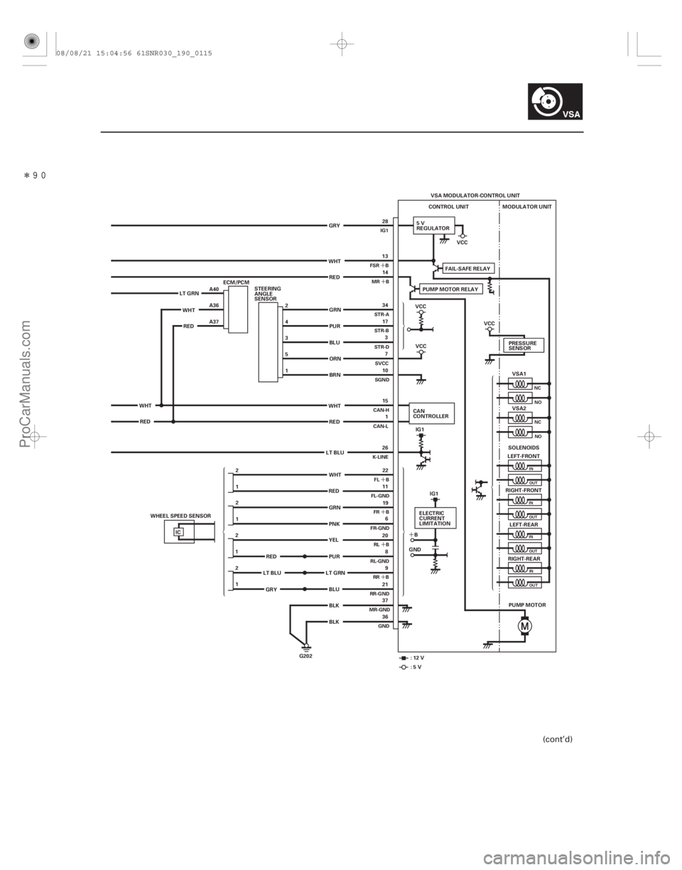
VSA MODULATOR-CONTROL UNIT
CONTROL UNIT
5V
REGULATOR MODULATOR UNIT
VSA1
VSA2
LEFT-FRONT
RIGHT-FRONT LEFT-REAR
RIGHT-REAR
PUMP MOTOR
G202 PRESSURE
SENSOR
SOLENOIDS
IC 13
14
22
11 19 6
20 8
9
21
37
36 34
17 3
7
10
15 1
26
1 2 1
2
2
1
1 2 28
WHT RED
GRN
PUR
BLU
ORN
BRN
WHT RED
LT BLU
GRN
PNK
BLK BLK
LT GRN
WHTRED A40
A36
A37
WHT RED 2
4
3
5
1
STEERING
ANGLE
SENSOR
PUR
LT GRN
RED
LT BLU
GRY PUMP MOTOR RELAY
FAIL-SAFE RELAY
VCC
VCC
IG1
CAN
CONTROLLER
:12V :5V VCC
ELECTRIC
CURRENT
LIMITATION
B
GND IG1
VCC
GRY
BLU YEL
RED
WHT
ECM/PCM
WHEEL SPEED SENSOR
NC NO
NCNO
IN
OUT
IN OUT
IN OUT
INOUT
FSR B MR B
FL B
FL-GND FR B
FR-GND
RL B
RL-GND RR B
RR-GND
MR-GND
GND
STR-A
STR-B
STR-D
SVCC
SGND
CAN-H
CAN-L
K-LINE IG1
(cont’d)
08/08/21 15:04:56 61SNR030_190_0115
ProCarManuals.com
DYNOMITE -2009-
Page 1608 of 2893
���
19-116VSA System Components
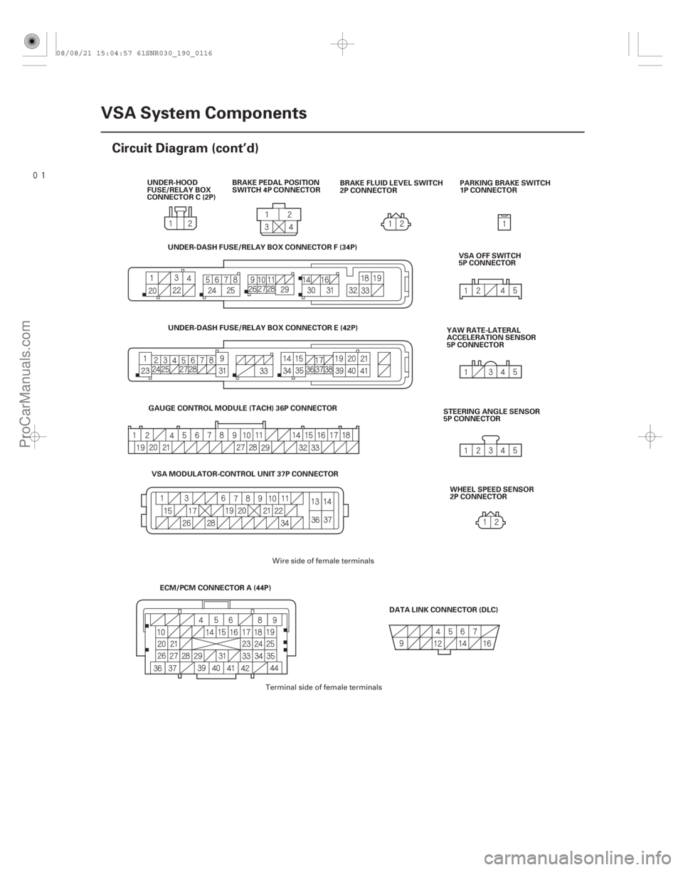
Circuit Diagram (cont’d)
BRAKE PEDAL POSITION
SWITCH 4P CONNECTOR
PARKING BRAKE SWITCH
1P CONNECTOR
DATA LINK CONNECTOR (DLC) VSA OFF SWITCH
5P CONNECTOR
YAW RATE-LATERAL
ACCELERATION SENSOR
5P CONNECTOR
STEERING ANGLE SENSOR
5P CONNECTOR
BRAKE FLUID LEVEL SWITCH
2P CONNECTOR
UNDER-HOOD
FUSE/RELAY BOX
CONNECTOR C (2P)
WHEEL SPEED SENSOR
2P CONNECTOR
ECM/PCM CONNECTOR A (44P)
GAUGE CONTROL MODULE (TACH) 36P CONNECTOR
VSA MODULATOR-CONTROL UNIT 37P CONNECTOR UNDER-DASH FUSE/RELAY BOX CONNECTOR F (34P)
UNDER-DASH FUSE/RELAY BOX CONNECTOR E (42P)
Wire side of female terminals
Terminal side of female terminals
08/08/21 15:04:57 61SNR030_190_0116
ProCarManuals.com
DYNOMITE -2009-
Page 1630 of 2893
�����(�#���������� �����
����������
�
���������)����
�µ
�µ �µ
�µ
�µ
�µ
DTC 51-11:
DTC 51-13: DTC 51-12:
YES
NO YES
NO
YES
NO
19-13819-138VSA Syste")
�(�#�'��������� �����
�������'���
�
�
�������)�����(�#�'��������� �����
�������'���
�
���������)����
�µ
�µ �µ
�µ
�µ
�µ
DTC 51-11:
DTC 51-13: DTC 51-12:
YES
NO YES
NO
YES
NO
19-13819-138VSA System Components
DTC Troubleshooting (cont’d)
Motor Lock
Motor Relay OFF Malfunction
Motor Lock Circuit Malfunction
1. Turn the ignition switch to ON (II).
2. Clear the DTC with the HDS.
3. Turn the ignition switch to LOCK (0), then turn it to
ON (II) again.
4. Wait 5 seconds.
5. Operate any one of the four solenoids, as listed, in the VSA FUNCTION TEST five times with the HDS.
-LFT FT SOLENOID
-RT FT SOLENOID
-LFT REAR SOLENOID
-RT REAR SOLENOID
6. Check for DTCs with the HDS.
Replace the VSA modulator-control unit
(see page 19-171).
Intermittent failure, the system is OK at this
time. 1. Turn the ignition switch to ON (II).
2. Clear the DTC with the HDS.
3. Turn the ignition switch to LOCK (0), then turn it to
ON (II) again.
4. Check for DTCs with the HDS.
Go to step 5.
Intermittent failure, the system is OK at this
time. Check for loose terminals at the VSA
modulator-control unit 37P connector. Refer to
intermittent failures troubleshooting (see page
19-98).
5. Turn the ignition switch to LOCK (0).
6. Check the No. 3 (30 A) fuse in the under-hood fuse/ relay box.
Go to step 7.
Reinstall the checked fuse, then go to step 14.
7. Disconnect the VSA modulator-control unit 37P connector (see step 2 on page 19-171).
I s DT C 5 1-11 or 5 1-13 i nd i cat ed ? I s DT C 5 1-12 i nd i cat ed ?
Isthefuseblown?
08/08/21 15:05:56 61SNR030_190_0138
ProCarManuals.com
DYNOMITE -2009-
Page 1631 of 2893
���
�´
�µ
�µ �µ
�µ
YES
NO YES
NO
19-139
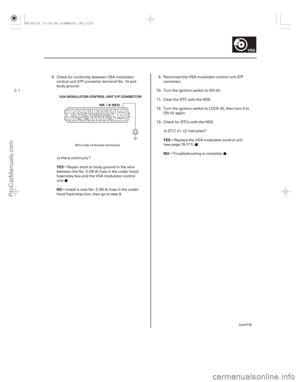
MR B (RED)
VSA MODULATOR-CONTROL UNIT 37P CONNECTOR
8. Check for continuity between VSA modulator-
control unit 37P connector terminal No. 14 and
body ground.
Repair short to body ground in the wire
between the No. 3 (30 A) fuse in the under-hood
fuse/relay box and the VSA modulator-control
unit.
Install a new No. 3 (30 A) fuse in the under-
hood fuse/relay box, then go to step 9. 9. Reconnect the VSA modulator-control unit 37P
connector.
10. Turn the ignition switch to ON (II).
11. Clear the DTC with the HDS.
12. Turn the ignition switch to LOCK (0), then turn it to ON (II) again.
13. Check for DTCs with the HDS.
Replace the VSA modulator-control unit
(see page 19-171).
Troubleshooting is complete.
(cont’d)
Wire side of female terminals
Is there continuity? I s DT C 5 1-12 i nd i cat ed ?
08/08/21 15:05:56 61SNR030_190_0139
ProCarManuals.com
DYNOMITE -2009-
Page 1632 of 2893
����
�´
�µ
�µ �µ
�µ
YES
NO YES
NO
DTC 52-12:
19-14019-140VSA System Components
DTC Troubleshooting (cont’d)
MR B (RED)
VSA MODULATOR-CONTROL U")
����
�(�#�'��������� �����
�������'�����
���������)����
�´
�µ
�µ �µ
�µ
YES
NO YES
NO
DTC 52-12:
19-14019-140VSA System Components
DTC Troubleshooting (cont’d)
MR B (RED)
VSA MODULATOR-CONTROL UNIT 37P CONNECTOR
14. Disconnect the VSA modulator-control unit 37P
connector (see step 2 on page 19- 171).
15. Measure the voltage between VSA modulator- control unit 37P connector terminal No. 14 and
body ground.
Check for loose terminals in the VSA
modulator-control unit 37P connector. If necessary,
substitute a known-good VSA modulator-control
unit (see page 19-171), and retest.
Repair open in the wire between the No. 3
(30 A) fuse in the under-hood fuse/relay box and
the VSA modulator-control unit. 1. Turn the ignition switch to ON (II).
2. Clear the DTC with the HDS.
3. Turn the ignition switch to LOCK (0), then turn it to
ON (II) again.
4. Operate any one of the four solenoids, as listed, in the VSA FUNCTION TEST five times with the HDS.
-LFT FT SOLENOID
-RT FT SOLENOID
-LFT REAR SOLENOID
-RT REAR SOLENOID
5. Check for DTCs with the HDS.
Replace the VSA modulator-control unit
(see page 19-171).
Intermittent failure, the system is OK at this
time.Motor Stuck OFF
Wire side of female terminals
Is there battery voltage? Is DTC 52-12 indicated?
08/08/21 15:05:56 61SNR030_190_0140
ProCarManuals.com
DYNOMITE -2009-
Page 1633 of 2893
����
�µ
�µ
�µ
�µ
DTC 53-01:
DTC 53-12:
YES
NO YES
NO
19-141
MR-GND (BLK)
VSA MODULATOR-CONTROL UNIT 37P CONNECTOR
Motor Relay Stuck ON 1
Motor Re")
���
�(�#�'��������� �����
�������'�������
�������)����
�µ
�µ
�µ
�µ
DTC 53-01:
DTC 53-12:
YES
NO YES
NO
19-141
MR-GND (BLK)
VSA MODULATOR-CONTROL UNIT 37P CONNECTOR
Motor Relay Stuck ON 1
Motor Relay Stuck ON 2
1. Turn the ignition switch to ON (II).
2. Clear the DTC with the HDS.
3. Turn the ignition switch to LOCK (0), then turn it to
ON (II) again.
4. Check for DTCs with the HDS.
Go to step 5.
Intermittent failure, the system is OK at this
time. Check for loose terminals at the VSA
modulator-control unit 37P connector. Refer to
intermittent failures troubleshooting (see page
19-98).
5. Turn the ignition switch to LOCK (0).
6. Disconnect the VSA modulator-control unit 37P connector (see step 2 on page 19- 171).7. Check for continuity between VSA modulator-
control unit 37P connector terminal No. 37 and
body ground.
Check for loose terminals in the VSA
modulator-control unit 37P connector. If necessary,
substitute a known-good VSA modulator-control
unit (see page 19-171), and retest.
Repair open in the wire between the VSA
modulator-control unit and body ground (G202).
Wire side of female terminals
I s DT C 5 3-01 or 5 3-12 i nd i cat ed ?
Is there continuity?
08/08/21 15:05:56 61SNR030_190_0141
ProCarManuals.com
DYNOMITE -2009-