Page 1445 of 2893
����
18-35
Upper Arm Removal/Installation
A A
B A
12x1.25mm
59 N·m
(6.0 kgf·m, 43 lbf·ft)
B
12x1.25mm
108 N·m
(11.0 kgf·m,
79.6 lbf·ft")
���
���
���
�(�#�'���������������
���������������
� �����)����
18-35
Upper Arm Removal/Installation
A A
B A
12x1.25mm
59 N·m
(6.0 kgf·m, 43 lbf·ft)
B
12x1.25mm
108 N·m
(11.0 kgf·m,
79.6 lbf·ft)
C
NOTE: There are two types of rear upper arms. Those
that are marked with ‘‘C’’ (A), and those with no marks.
Be sure to use the correct alignment specifications.
1. Raise the rear of the vehicle, and support it with safety stands in the proper locations (see page
1-11).
2. Remove the rear wheel.
3. Position a floor jack at the connecting point of the trailing arm (A) and the knuckle (B). Raise the floor
jack until the suspension begins to compress. 4. Remove the flange bolts (A) from the vehicle.
NOTE: Use new flange bolts during reassembly.
5. Remove the flange bolt (B) from the knuckle, and remove the upper arm (C).
NOTE: Use the new flange bolt during reassembly.
6. Install the upper arm in the reverse order of removal, and note these items:
First install all of the components, and lightly tighten the bolts, then raise the suspension to
load it with the vehicle’s weight before fully
tightening to the specified torque values.
Before installing the wheel, clean the mating surfaces of the brake disc and the inside of the
wheel.
7. Check the wheel alignment, and adjust it if necessary (see page 18-5).
Replace. Replace.
08/08/21 14:57:43 61SNR030_180_0035
ProCarManuals.com
DYNOMITE -2009-
Page 1446 of 2893
����
18-36 Rear Suspension
Trailing Arm Removal/Installation
B
A
8x1.25mm
22 N·m
(2.2 kgf·m, 16 lbf·ft)
A
B A
12x1.25mm
59 N·m
(6.0 kgf�")
���
�������
�(�#�'���������������
���������������
� �����)����
18-36 Rear Suspension
Trailing Arm Removal/Installation
B
A
8x1.25mm
22 N·m
(2.2 kgf·m, 16 lbf·ft)
A
B A
12x1.25mm
59 N·m
(6.0 kgf·m,
43 lbf·ft)
1. Raise the rear of the vehicle, and support it with
safety stands in the proper locations (see page
1-11).
2. Remove the rear wheel.
3. Remove the rear floor under cover (see page 20-174).
4. Remove the parking brake cable mounting bolt (A) from the trailing arm (B).
5. Position a floor jack at the connecting point of the trailing arm (A) and the knuckle (B). Raise the floor
jack until the suspension begins to compress.
6. Remove the knuckle with the hub bearing unit (see page 18-33).
7. Disconnect the stab ilizer link from the trailing arm
(see page 18-37).
8. Remove the rear spring (see page 18-43). 9. Remove the trailing arm rear m
ounting bolt (A).
NOTE: Use the new mounting bolt during
reassembly.
10. Lower the jack, and remove the trailing arm.
Replace.
08/08/21 14:57:44 61SNR030_180_0036
ProCarManuals.com
DYNOMITE -2009-
Page 1447 of 2893
����
18-3718-37
Stabilizer Link Removal/Installation
A
Except Type S model:
10x1.25mm
39 N·m
(4.0 kgf·m, 29 lbf·ft) C
D E
F
GH
B
10x1.25mm
39 N·m")
���
�(�#�'���������������
���������������
� �����)����
18-3718-37
Stabilizer Link Removal/Installation
A
Except Type S model:
10x1.25mm
39 N·m
(4.0 kgf·m, 29 lbf·ft) C
D E
F
GH
B
10x1.25mm
39 N·m
(4.0 kgf·m, 29 lbf·ft)
Type S model:
10x1.25mm
38 N·m
(3.9 kgf·m, 28 lbf·ft)
11. Install the trailing arm in the reverse order of
removal, and note these items:
First install all of the components, and lightly tighten the bolts, then raise the suspension to
load it with the vehicle’s weight before fully
tightening to the specified torque values.
Check the brake hose for interference and twisting.
Before installing the wheel, clean the mating surfaces on the brake disc and the inside of the
wheel.
12. Check the wheel alignment, and adjust it if necessary (see page 18-5). 1. Raise the rear of the vehicle, and support it with
safety stands in the proper locations (see page
1-11).
2. Remove the rear wheel.
3. Remove the self-locking nut (A) and the flange nut (B) while holding the respective joint pin (C) with a
hex wrench (D), then remove the stabilizer link (E).
4. Install the stabilizer link on the stabilizer bar (F) and trailing arm (G) with the joint pins set at the center
of their range of the movement.
NOTE: The stabilizer link has a paint mark (H). Align
the paint mark on the stabilizer link facing rearward.
5. Install the new self-locking nut and the new flange nut, and tighten them to the specified torque values
while holding the respective joint pin with a hex
wrench.
6. Clean the mating surfaces of the brake disc and the inside of the wheel, then install the rear wheel.
7. Test-drive the vehicle.
8. After 5 minutes of driving, torque the self-locking nut again to the specified torque values.
Replace.
Replace.
Replace.
08/08/21 14:57:44 61SNR030_180_0037
ProCarManuals.com
DYNOMITE -2009-
Page 1448 of 2893
����
18-3718-37
Stabilizer Link Removal/Installation
A
Except Type S model:
10x1.25mm
39 N·m
(4.0 kgf·m, 29 lbf·ft) C
D E
F
GH
B
10x1.25mm
39 N·m")
���
�(�#�'���������������
���������������
� �����)����
18-3718-37
Stabilizer Link Removal/Installation
A
Except Type S model:
10x1.25mm
39 N·m
(4.0 kgf·m, 29 lbf·ft) C
D E
F
GH
B
10x1.25mm
39 N·m
(4.0 kgf·m, 29 lbf·ft)
Type S model:
10x1.25mm
38 N·m
(3.9 kgf·m, 28 lbf·ft)
11. Install the trailing arm in the reverse order of
removal, and note these items:
First install all of the components, and lightly tighten the bolts, then raise the suspension to
load it with the vehicle’s weight before fully
tightening to the specified torque values.
Check the brake hose for interference and twisting.
Before installing the wheel, clean the mating surfaces on the brake disc and the inside of the
wheel.
12. Check the wheel alignment, and adjust it if necessary (see page 18-5). 1. Raise the rear of the vehicle, and support it with
safety stands in the proper locations (see page
1-11).
2. Remove the rear wheel.
3. Remove the self-locking nut (A) and the flange nut (B) while holding the respective joint pin (C) with a
hex wrench (D), then remove the stabilizer link (E).
4. Install the stabilizer link on the stabilizer bar (F) and trailing arm (G) with the joint pins set at the center
of their range of the movement.
NOTE: The stabilizer link has a paint mark (H). Align
the paint mark on the stabilizer link facing rearward.
5. Install the new self-locking nut and the new flange nut, and tighten them to the specified torque values
while holding the respective joint pin with a hex
wrench.
6. Clean the mating surfaces of the brake disc and the inside of the wheel, then install the rear wheel.
7. Test-drive the vehicle.
8. After 5 minutes of driving, torque the self-locking nut again to the specified torque values.
Replace.
Replace.
Replace.
08/08/21 14:57:44 61SNR030_180_0037
ProCarManuals.com
DYNOMITE -2009-
Page 1449 of 2893
����
18-38Rear Suspension
Stabilizer Bar Replacement
B
C
D
A
Except Type S model:
8x1.25mm
22N·m(2.2kgf·m,16lbf·ft)
Type S model:
10x1.25mm")
����
����
�(�#�'���������������
���������������
� �����)����
18-38Rear Suspension
Stabilizer Bar Replacement
B
C
D
A
Except Type S model:
8x1.25mm
22N·m(2.2kgf·m,16lbf·ft)
Type S model:
10x1.25mm
49 N·m
(5.0 kgf·m, 36 lbf·ft)
E
10x1.25mm
39 N·m
(4.0 kgf·m,
29 lbf·ft)
A
1. Raise the rear of the vehicle, and support it with
safety stands in the proper locations (see page
1-11).
2. Remove the rear wheels.
3. Disconnect both stab ilizer links from the stabilizer
bar (see page 18-37).
4. Remove the flange bolts (A) and the bushing holders (B), then remove the bushings (C) and the
stabilizer bar (D).
NOTE: During installation, align the paint marks (E)
on the stabilizer bar with the sides of the bushings.
5. Replace the stabilizer bar bracket (A) if necessary. 6. Install the stabilizer bar in the reverse order of
removal, and note these items:
Note the right and left direction of the stabilizer bar.
Refer to stabilizer link removal/installation to connect the stab ilizer bar to the links (see page
18-37).
Before installing the wheel, clean the mating surfaces of the brake disc and inside of the wheel.
7. Check the wheel alignment, and adjust it if necessary (see page 18-5).
08/08/21 14:57:45 61SNR030_180_0038
ProCarManuals.com
DYNOMITE -2009-
Page 1451 of 2893
����
��������
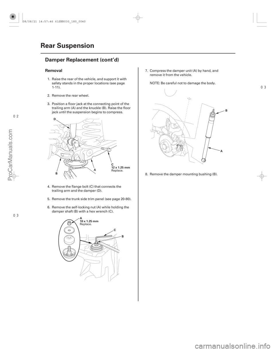
Removal
18-40Rear Suspension
Damper Replacement (cont’d)
C
12x1.25mm
A
B
D
A
10x1.25mm B
C A
B
1. Raise the rear of the vehicle, and support it with
safety stands in the proper locations (see page
1-11).
2. Remove the rear wheel.
3. Position a floor jack at the connecting point of the trailing arm (A) and the knuckle (B). Raise the floor
jack until the suspension begins to compress.
4. Remove the flange bolt (C) that connects the trailing arm and the damper (D).
5. Remove the trunk side trim panel (see page 20-80).
6. Remove the self-locking nut (A) while holding the damper shaft (B) with a hex wrench (C). 7. Compress the damper unit (A) by hand, and
remove it from the vehicle.
NOTE: Be careful not to damage the body.
8. Remove the damper mounting bushing (B).
Replace.
Replace.
08/08/21 14:57:46 61SNR030_180_0040
ProCarManuals.com
DYNOMITE -2009-
Page 1453 of 2893
����
�������
�(�#�'���������������
���������������
� �����)����
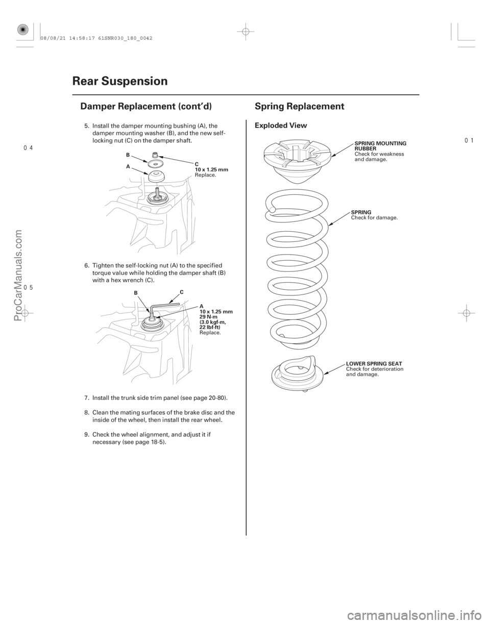
Exploded View
18-4218-42 Rear Suspension
Damper Replacement (cont’d) Spring Replacement
A
B
C
10x1.25mm
B C
A
10x1.25mm
29 N·m
(3.0 kgf·m,
22 lbf·ft) SPRING MOUNTING
RUBBER
SPRING
LOWER SPRING SEAT
5. Install the damper mounting bushing (A), the damper mounting washer (B), and the new self-
locking nut (C) on the damper shaft.
6. Tighten the self-locking nut (A) to the specified torque value while holding the damper shaft (B)
with a hex wrench (C).
7. Install the trunk side trim panel (see page 20-80).
8. Clean the mating surfaces of the brake disc and the inside of the wheel, then install the rear wheel.
9. Check the wheel alignment, and adjust it if necessary (see page 18-5).
Replace.
Replace. Check for weakness
and damage.
Check for damage.
Check for deterioration
and damage.
08/08/21 14:58:17 61SNR030_180_0042
ProCarManuals.com
DYNOMITE -2009-
Page 1454 of 2893
����
�������
�(�#�'���������������
���������������
� �����)����
Exploded View
18-4218-42 Rear Suspension
Damper Replacement (cont’d) Spring Replacement
A
B
C
10x1.25mm
B C
A
10x1.25mm
29 N·m
(3.0 kgf·m,
22 lbf·ft) SPRING MOUNTING
RUBBER
SPRING
LOWER SPRING SEAT
5. Install the damper mounting bushing (A), the damper mounting washer (B), and the new self-
locking nut (C) on the damper shaft.
6. Tighten the self-locking nut (A) to the specified torque value while holding the damper shaft (B)
with a hex wrench (C).
7. Install the trunk side trim panel (see page 20-80).
8. Clean the mating surfaces of the brake disc and the inside of the wheel, then install the rear wheel.
9. Check the wheel alignment, and adjust it if necessary (see page 18-5).
Replace.
Replace. Check for weakness
and damage.
Check for damage.
Check for deterioration
and damage.
08/08/21 14:58:17 61SNR030_180_0042
ProCarManuals.com
DYNOMITE -2009-