Page 2617 of 2893
�����(�#������#��� �����
�������#���������������)����
�µ
�µ �µ
�µ
DTC 2702: DTC 2703:
YES
NO
YES
NO
23-33123-331
GPS Diag: Receiver in Navi ECUAircon")
�(�#�'�����#��� �����
�������#���������������)�����(�#�'�����#��� �����
�������#���������������)����
�µ
�µ �µ
�µ
DTC 2702: DTC 2703:
YES
NO
YES
NO
23-33123-331
GPS Diag: Receiver in Navi ECUAircon Diag
NOTE:
Check the vehicle battery condition first.
Before you troubleshoot, make sure to follow the general troubleshooting information (see page
23-266).
Make sure the vehicle is parked outside, away from buildings.
Check for electronic aftermarket accessories (possibly hidden) mounted near the GPS antenna or
the navigation unit.
1. Clear the hard error code (see page 23-274).
2. Turn the ignition switch to LOCK (0), and then back to ON (II).
3. Go into the Diagnostic Menu, and Select the Self- Diagnosis Mode in the Select Diagnosis Items
Menu (see page 23-297).
4. Select the System Links, then select the GPS Ant.
Intermittent failure, the system is OK at this
time.
Replace the navigation unit (see page 23-355). NOTE:
Check the vehicle battery condition first.
Check for B-CAN DTCs and resolve them before troubleshooting.
Before you troubleshoot, make sure to follow the general troubleshooting information (see page
23-266).
DTC 2703 can be stored when the ignition switch is at ACCESSORY (I). With the ignition switch is in
ACCESSORY (I), the climate control unit is turned off
and the navigation unit loses communication and
stores DTCs. Therefore, there is a possibility that the
system is normal even DTC 2703 is stored. Check
system links (see page 23-297) with the engine
running, and if it shows normal, the system is OK at
this time. If not, do this troubleshooting.
1. Clear the hard error code (see page 23-274).
2. Turn the ignition switch to LOCK (0), and then back to ON (II).
3. Go into the Diagnostic Menu, and Select the Self- Diagnosis Mode in the Select Diagnosis Items
Menu (see page 23-297).
4. Check the System Links.
Go to step 5.
Intermittent failure, the system is OK at this
time.
5. Turn the ignition switch to LOCK (0).
(cont’d)
Is Receiver in Navi ECU OK indicated? Is the Air con icon r ed?
08/08/21 14:17:48 61SNR030_230_0334
ProCarManuals.com
DYNOMITE -2009-
Page 2618 of 2893

NAVIGATION UNIT CONNECTOR D (12P)
AC SI
(YEL)
AC CLK
(BLU) AC SO
(RED)
JUMPER WIRE CLIMATE C")
����
�����
�����
�µ
�µ
�µ
�µ
YES
NO
YES
NO
23-332Navigation System
DTC Troubleshooting (cont’d)
NAVIGATION UNIT CONNECTOR D (12P)
AC SI
(YEL)
AC CLK
(BLU) AC SO
(RED)
JUMPER WIRE CLIMATE CONTROL UNIT CONNECTOR A (32P)
AC SO (RED)AC SI (YEL)
AC CLK (BLU)
JUMPER WIRE
NAVIGATION UNIT CONNECTOR D (12P) AC SI
(YEL)
AC CLK
(BLU) AC SO
(RED)
6. Disconnect navigation unit connector D (12P).
7. Connect navigation unit connector D (12P)
terminals No. 5, No. 6, and No. 12 with a jumper
wire.
8. Turn the ignition switch to ON (II).
9. Press the RECIRCULATION and OFF buttons. Replace the navigation unit (see page 23-355).
Go to step 10.
10. Turn the ignition switch to LOCK (0), then disconnect the jumper wire.
11. Disconnect climate control unit connecter A (32P). 12. Connect climate control unit connector A (32P)
terminals No. 28, No. 29, and No. 30 with a jumper
wire.
13. Check for continuity between navigation unit connector D (12P) terminals No. 5 and No. 6, then
between terminals No. 5 and No. 12.
Go to step 14.
Repair open in the wire(s) between the
navigation unit and the climate control unit.
14. Disconnect the jumper wire.
Wire side of female terminals Wire side of female terminals
Wire side of female terminals
Does the RECIRCULAT ION indicator turn on? Is there continuity?
08/08/21 14:17:48 61SNR030_230_0335
ProCarManuals.com
DYNOMITE -2009-
Page 2619 of 2893
����������
�µ
�µ �µ
�µ
YES
NO From terminal To terminals
YES
NO
23-333
NAVIGATION UNIT CONNECTOR D (12P) AC SI
(YEL)
AC CLK
(BLU) AC SO
(RED)
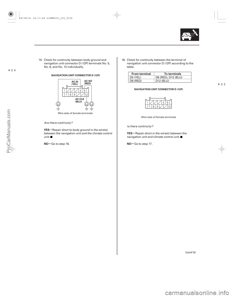
NAVIGATION UNIT CONNECTOR D (12P)
15. Check for continuity between body ground andnavigation unit connector D (12P) terminals No. 5,
No. 6, and No. 12 individually.
Repair short to body ground in the wire(s)
between the navigation unit and the climate control
unit.
Go to step 16. 16. Check for continuity between the terminal of
navigation unit connector D (12P) according to the
table.
D5 (YEL) D6 (RED), D12 (BLU)
D6 (RED) D12 (BLU)
Repair short in the wire(s) between the
navigation unit and climate control unit.
Go to step 17.
(cont’d)
Wire side of female terminals Wire side of female terminals
Ar e t her e cont i nui t y ?Is there continuity?
08/08/21 14:17:49 61SNR030_230_0336
ProCarManuals.com
DYNOMITE -2009-
Page 2620 of 2893
����
�µ
�µ �µ
�µ
�µ
�µ
YES
NO
YES
NO
YES
NO
DTC 2705:
23-33423-334Navigation System
DTC Troubleshooting (cont’d)
NAVIGATION UNIT CONNECTOR")
�����
�(�#�'�����#��� �����
�������#���������������)����
�µ
�µ �µ
�µ
�µ
�µ
YES
NO
YES
NO
YES
NO
DTC 2705:
23-33423-334Navigation System
DTC Troubleshooting (cont’d)
NAVIGATION UNIT CONNECTOR D (12P)
AC SI
(YEL)
AC CLK
(BLU) AC SO
(RED)
17. Turn the ignition switch to ON (II).
18. Measure the voltage between body ground and
navigation unit connector D (12P) terminals No. 5,
No. 6, and No. 12 individually.
Repair short to power in the wire(s) between
the navigation unit and the climate control unit.
Replace the climate control unit (see page
21-75). NOTE: Before you troubleshoot, make sure to follow the
general troubleshooting information (see page 23-266).
1. Clear the hard error code (see page 23-274).
2. Turn the ignition switch to LOCK (0), and then back to ON (II).
3. Go into the Diagnostic Menu, and Select the Self- Diagnosis Mode in the Select Diagnosis Items
Menu (see page 23-297).
4. Select the System Links.
Go to step 5.
Intermittent failure, the system is OK at this
time.
5. Turn the ignition switch to LOCK (0).
6. Connect the HDS to the DLC (see page 23-359).
7. Clear the DTCs with the HDS.
8. Turn the ignition switch to LOCK (0), and then back to ON (II).
9. Check for DTCs with the HDS.
Do the HFL DTC troubleshooting.
Go to step 10.
10. Turn the ignition switch to LOCK (0).
11. Disconnect navigation unit connector B (24P).
12. Disconnect the HandsFr eeLink control unit 28P
connector.HFL Diag
Wire side of female terminals
I s t her e v ol t age abov e 0.2 V ? Is the HF L icon red?
Ar e t her e any H F L DT Cs i nd i cat ed ?
08/08/21 14:17:49 61SNR030_230_0337
ProCarManuals.com
DYNOMITE -2009-
Page 2633 of 2893
����
�µ
�µ
�µ
�µ
YES
NO
YES
NO
System always comes up in in-line
diagnostic mode
23-34723-347
In Line Diag
123
456
789
0
Navi ECU
Display X")
�µ�Î�
��
�(�#�'�����#���������
�����������������������)����
�µ
�µ
�µ
�µ
YES
NO
YES
NO
System always comes up in in-line
diagnostic mode
23-34723-347
In Line Diag
123
456
789
0
Navi ECU
Display XXXXCorrect PIN
GPS Antenna
RR Camera RadioXM
HFL
A/C
Exit Diag
Start Diag
BACK
Delete Done
KA
2. Turn the ignition switch to ON (II).
3. Select the Self-Diagnosis mode.
4. Check for error code in the Error History.
Refer to the Hard Error Code
troubleshooting.
Go to step 5.
5. Substitute a known-good climate control unit. Reconnect all connectors, and retest.
Replace the original climate control unit
(see page 21-75).
Replace the navigation unit (see page 23-355). 1. When a navigation unit is powered up for the first
time at the factory, the factory diagnosis screen (In
Line Diag) appears. Normally the factory performs
the steps necessary to verify proper operation, and
terminate the factory diagnostic. Until the proper
confirmation sequence is performed, the screen
will appear every time the vehicle is started.
2. Follow the steps to prevent the screen from showingupinthefuture:
Hold down the buttons (Menu, Map/Guide, and Cancel) for about 5 seconds. The Select
Diagnosis Items screen appears.
Hold down the Map/Guide button for 5 10 seconds. A screen with a Complete button,
appears.
Touch Complete, and then the Return button (the system may re-boot).
Restart the vehicle, and confirm normal operation by completing the PDI of the
navigation system Service Bulletin.
Are there any Hard Error Code stored?
Does t he sy mpt om go aw ay ?
08/08/21 14:17:52 61SNR030_230_0350
ProCarManuals.com
DYNOMITE -2009-
Page 2663 of 2893

�����
�´�µ�´ �µ
�´�µ �´ �µ
�´�µ
23-375
3
27
HANDSFREELINK CONTROL UNIT
MIC
SIG
MIC
SIG HFL
MUTE
BRN
YEL
HFL-NAVIGATION
MICROPHONE HFL
ICON
TELEM
SIG TELEM
SIG
12 13 14
D8 D7 D9 B8 B20 B21 B9
GRY
MIC
SIG MIC
SIG HFL
MUTEHFL
ICONTELEM
SIG TELEM
SIG
GRN RED LT BLU LT GRN BLU PNK
GRY
MIC
SH
GRY
B-CAN
18
PNK
PNK
LT BLU
MICU PNK
Q6
DATA LINK
CONNECTOR
(DLC)
GAUGE CONTROL
MODULE (TACH)
CLIMATE CONTROL
UNIT
28
191125 26
Q8
UNDER-DASH FUSE/RELAY BOX
AUDIO
REMOTE
GND
A5
BRN
A 7B24
B12B10
GRY
RED WHT
6
20 HFL/NAVI
COMM2
B23
BLK GRN
21B11
GRY8
HFL/NAVI
COMM1
HFL/NAVI
COMM3HFL/NAVI
COMM4HFL/NAVI
COMM SH
HFL/NAVI
COMM2
HFL/NAVI
COMM1 HFL/NAVI
COMM3
HFL/NAVI
COMM4HFL/NAVI
COMM SH MIC
SIG SH
TELEM
SIG SH
MIC MIC
NAVIGATION UNIT
12
ORN
MOONROOF
SWITCH
3 *: The shielded wires have a heat-shrunk tube
insulating the outside of the wire. The color
of the insulating tube, typically black or dark gray,
may not match the color of the wire listed on the
schematic.
: CAN line
: Shielding
*
*
*
*
*
08/08/21 14:18:40 61SNR030_230_0378
ProCarManuals.com
DYNOMITE -2009-