Page 2250 of 2893
������(�#�'�����"���������
�����������������������)����
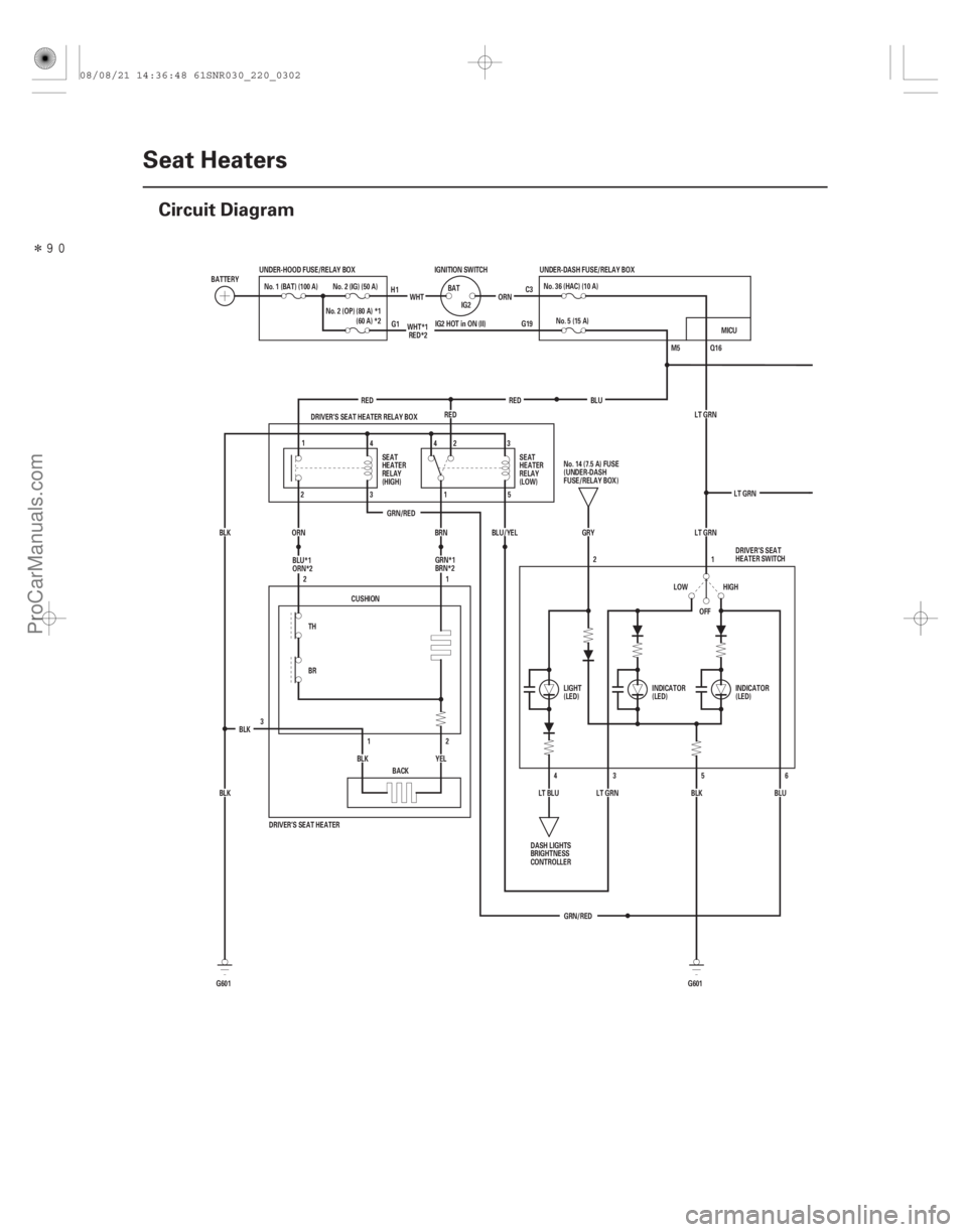
22-300Seat Heaters
Circuit Diagram
Q16
IG2 HOT in ON (II) G19 C3
M5
LT GRN
GRN/RED LT GRN
OFF 1
2
GRN/RED LT GRN
6
5
3
BLU
BLK HIGH
LOW
4
LT BLU GRY
LT GRN
DRIVER’S SEAT HEATER
3
YEL
BLK
BLK BLK CUSHION
1
2
2
1
BACK
BR TH DRIVER’S SEAT HEATER RELAY BOX
BLU/YEL
BRN
ORN
BLK RED
RED
RED No. 5 (15 A)
No.36(HAC)(10A)
G601
G601 IGNITION SWITCH
IG2
BAT
ORN
WHT
UNDER-HOOD FUSE/RELAY BOX
No. 2 (IG) (50 A)
No. 1 (BAT) (100 A)
BATTERY UNDER-DASH FUSE/RELAY BOX
SEAT
HEATER
RELAY
(HIGH) SEAT
HEATER
RELAY
(LOW)
No.14(7.5A)FUSE
(UNDER-DASH
FUSE/RELAY BOX)
DASH LIGHTS
BRIGHTNESS
CONTROLLER LIGHT
(LED)
INDICATOR
(LED)DRIVER’S SEAT
HEATER SWITCH
INDICATOR
(LED)
H1
G1
1 4
2 343
1 5
2
No. 2 (OP) (80 A) *1
(60 A) *2 WHT*1
RED*2
BLU
BLU*1
ORN*2 GRN*1
BRN*2 MICU
08/08/21 14:36:48 61SNR030_220_0302
ProCarManuals.com
DYNOMITE -2009-
Page 2251 of 2893
�����
�µ
�µ
�¦�µ �µ �§
�¦�µ �µ�§
�¦�µ �µ�§ �¦�µ �µ�§
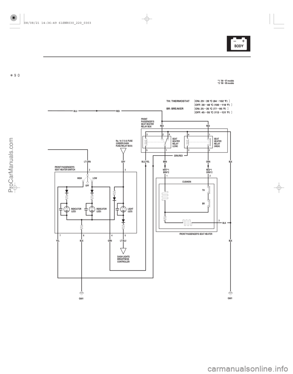
22-301
GRN/REDRED
OFF 3
BLU
RED
BLK
ORN
BRN
BLU/YEL
TH
BR2
1
CUSHION
BLKBLK
FRONT PASSENGER’S SEAT HEATER
LT GRN GRY
LT BLU5
LOW
HIGH
BLK
YEL 4
6
7
GRN3
2
FRONT PASSENGER’S
SEAT HEATER SWITCH
DASH LIGHTS
BRIGHTNESS
CONTROLLER
No. 14 (7.5 A) FUSE
(UNDER-DASH
FUSE/RELAY BOX)
SEAT
HEATER
RELAY
(LOW)SEAT
HEATER
RELAY
(HIGH)
FRONT
PASSENGER’S
SEAT HEATER
RELAY BOX
INDICATOR
(LED) INDICATOR
(LED) LIGHT
(LED)32
4
5 1 4
1
3 2
RED
WHT*1BRN*2 *1: ’06 07 models
*2: ’08 09 models
RED*1
ORN*2
G601
G601
TH: THERMOSTAT
BR: BREAKER ON: 29 39 °C (84 102 °F)
OFF: 38 48 °C (100 118 °F)
OFF: 45 55 °C (113 131 °F) ON: 25 35 °C (77 95 °F)
08/08/21 14:36:49 61SNR030_220_0303
ProCarManuals.com
DYNOMITE -2009-
Page 2252 of 2893
���� ���
�(�#������\"���������
���������������
�������)����
�¦�§�¦�§�¦�§�¦�§�¦�§�¦�§
�¦�§
Driver’s
22-30222-302 Seat Heaters
Swi")
���
�����(�#�'�����"���������
�������������
�
�������)���� ���
�(�#�'�����"���������
���������������
�������)����
�¦�§�¦�§�¦�§�¦�§�¦�§�¦�§
�¦�§
Driver’s
22-30222-302 Seat Heaters
Switch Test/Replacement
Seat Heater Test
A
Driver’s seat heater switch
Front passenger’s seat heater switch
Terminal
Position
ON 1
HIGH LOW
OFF 2
2
3 3
4 4
5 5
6 6
7
: Front passenger’s seat heater switch A
B
1. Remove the center console front panel (see page20-92).
2. Disconnect the 6P (or 7P ) connector from the seat heater switch (A), then remove the switch.
*: Front passenger’s seat heater switch
3. Check for continuity between the terminals in each switch position according to the table.
4. If the continuity is not as specified, replace the switch.
5. Install the seat heater switch in the reverse order of removal. 1. Remove the driver’s seat (see page 20-118).
2. Disconnect the 3P connector (A) and 2P connector
(B) from the seat heater.
3. Check for continuity between seat-back heater 2P connector (female terminals) terminals No. 1 and
No. 2. There should be continuity.
Terminal side of
male terminals
Wire side of
female terminals
08/08/21 14:36:49 61SNR030_220_0304
ProCarManuals.com
DYNOMITE -2009-
Page 2253 of 2893

����
����
Front Passenger’s
22-303
SEAT-CUSHION HEATER 3P CONNECTOR
SEAT-BACK HEATER 2P CONNECTOR A
4. Reconnect the 2P connector.
5. Check for continuity between seat-cushion heater
3P connector (male terminals) terminal No. 1 and
seat-back heater 2P connector (female terminals)
terminal No. 2, and seat-cushion heater 3P
connector (male terminals) terminals No. 2 and
No. 3. There should be continuity.
6. If the continuity is not as specified, replace the appropriate seat heater. 1. Remove the front passenger’s seat (see page
20-118).
2. Disconnect the 3P connector (A) from the seat heater.
3. Check for continuity between seat-cushion heater 3P connector (male terminals) terminals No. 1 and
No. 3, and seat-cushion heater 3P connector (male
terminals) terminals No. 2 and No. 3. There should
be continuity.
4. If the continuity is not as specified, replace the seat heater.
Terminal side of male terminals
Wire side of female terminals Terminal side of
male terminals
08/08/21 14:36:49 61SNR030_220_0305
ProCarManuals.com
DYNOMITE -2009-
Page 2699 of 2893
���������
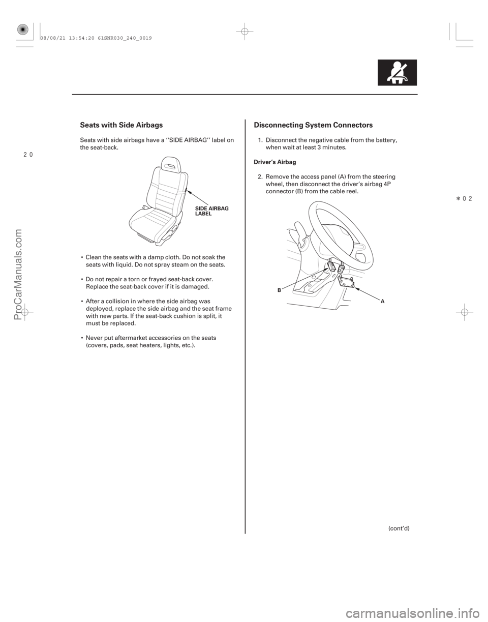
Seats with Side AirbagsDisconnecting System Connectors
Driver’s Airbag
24-19
SIDE AIRBAG
LABEL
A
B
Seats with side airbags have a ‘‘SIDE AIRBAG’’ label on
the seat-back.
Clean the seats with a damp cloth. Do not soak the seats with liquid. Do not spray steam on the seats.
Do not repair a torn or frayed seat-back cover. Replace the seat-back cover if it is damaged.
After a collision in where the side airbag was deployed, replace the side airbag and the seat frame
with new parts. If the seat-back cushion is split, it
must be replaced.
Never put aftermarket accessories on the seats (covers, pads, seat heaters, lights, etc.). 1. Disconnect the negative cable from the battery,
when wait at least 3 minutes.
2. Remove the access panel (A) from the steering wheel, then disconnect the driver’s airbag 4P
connector (B) from the cable reel.
(cont’d)
08/08/21 13:54:20 61SNR030_240_0019
ProCarManuals.com
DYNOMITE -2009-
Page 2707 of 2893
���
24-27
ODS Unit Calibration
A
When you replace the SRS unit, front passenger’s
weight sensors or ODS unit, calibrate the ODS unit.
While calibra")
�����(�#�'�������������������������������
�������)���
24-27
ODS Unit Calibration
A
When you replace the SRS unit, front passenger’s
weight sensors or ODS unit, calibrate the ODS unit.
While calibrating the ODS unit, observe these
precautions: Make sure all components of the front passenger’s seat are correctly installed.
Make sure nothing is on or under the front passenger’s seat.
Make sure there is nothing in the front passenger’s seat-back pocket.
Keep the windows and moonroof closed.
Do all calibration procedures except, test-driving, in the service bay.
Make sure the vehicle is on level gr ound.
Keep the A/C and the heater off.
Do not touch the front passenger’s seat during calibration, unless you are prompted to or when you
have completed the calibration.
Do not expose the front passenger’s seat to sudden temperature changes.
1. Position the front passenger’s seat to the rearmost position, and adjust the seat-back to the
forwardmost position. Do not move the seat from
these positions.
2. Make sure the ignition switch is in LOCK (0).
3. Connect the HDS to the data link connector (DLC) (A).
4. Turn the ignition switch to ON (II).
5. Make sure the HDS communicates with the vehicle and the SRS unit. If it does not communicate,
troubleshoot the DLC circuit (see page 11- 204).6. Drive the vehicle, and accelerate to 20 mph
(36 km/h), then stop on level ground.
7. From the Main Menu, select SRS, then Calibration, then Misc Test, then select SWS INITIALIZATION,
and follow the prompts until the calibration is
complete.
08/08/21 13:54:23 61SNR030_240_0027
ProCarManuals.com
DYNOMITE -2009-
Page 2708 of 2893
����
Pre-operation Check Set-up After Replacing Front Passenger’s Seat
Component(s)
24-28SRS
ODS Unit Operation Check
A
Check the ODS operation aft")
���
�(�#�'�������������������������������
�"�����)����
Pre-operation Check Set-up After Replacing Front Passenger’s Seat
Component(s)
24-28SRS
ODS Unit Operation Check
A
Check the ODS operation after any of these actions.
Replacement of front passenger’s seat component(s) (except ODS unit and/or weight sensors)
After a vehicle collision
SRS unit replacement
Make sure all the components of the front passenger’s seat are correctly installed.
Position the front passenger’s seat to the rearmost position.
Adjust the seat-back to the forwardmost position.
Do not move the seat from this position.
Make sure nothing is on or under the front passenger’s seat.
Make sure there is nothing in the front passenger’s seat-back pocket.
Keep the windows and moonroof closed.
Do all calibration procedures, except test-driving, in the service bay.
Make sure the vehicle is on level gr ound.
Turn the heater and the A/C off.
Do not touch the front passenger’s seat during the calibration, unless you are prompted to or until you
have completed the operation check.
Do not expose the front passenger’s seat to sudden temperature changes.
Make sure all aftermarket devices such as amplifiers, fluorescent lights, air purifies, CB or HAM radios, etc.
are turned off. 1. Make sure the ignition switch is in LOCK (0).
2. Connect the HDS to the data link connector (DLC)
(A).
3. Turn the ignition switch to ON (II).
4. Make sure the HDS communicates with the vehicle and the SRS unit. If it does not communicate,
troubleshoot the DLC circuit (see page 11-204).
5. Drive the vehicle, accelerate to 20 mph (36 km/h), then stop on level ground.
6. From the HDS Main Menu, select SRS, then Inspection. In the HDS Inspection Menu, select
SEAT OUTPUT CHK and follow the prompts until
the ODS unit operation check is complete.
08/08/21 13:54:23 61SNR030_240_0028
ProCarManuals.com
DYNOMITE -2009-
Page 2720 of 2893
���� ’06 model
24-40SRS
Circuit Diagram
GRN
BLU YEL
214 Q
E
G504
G602
BLK
LT GRN*
BLK*
BLK*
ORN*
LT BLU*
WHT*
RED* BLU*RED*
YEL*
2 1
G506 5
22
23")
�Î�����(�#�'���������������������������������������)���� ’06 model
24-40SRS
Circuit Diagram
GRN
BLU YEL
214 Q
E
G504
G602
BLK
LT GRN*
BLK*
BLK*
ORN*
LT BLU*
WHT*
RED* BLU*RED*
YEL*
2 1
G506 5
22
23 13 BLU
MICURED
2
4 MICU
GRY
YEL YEL
3
1
17 Vs
Vo
Vs
Vo
Vs
Vo
Vs
Vo BLU
BRN
5
10 15
GRY
123 3 21
LT GRN
16
11 6
GRY
BLU
GRN RED
4
914
WHT
123
321
BLK
13
83
RED
BRN MAIN CIRCUIT
VB
VA
WHT
GAUGE CONTROL MODULE (TACH)
BLK
412 SRS UNIT
ODS UNIT
7112 No. 9
(7.5 A) (7.5 A)
No. 10
No. 11
(10 A)
8
9 41
BRN
BLK
YEL
BLU GRN J
BATTERY
BAT
IG1
IGNITION SWITCH
UNDER-DASH FUSE/RELAY BOX
BLK
GRN
WHT BRN
A17
DRIVE CIRCUIT DRIVE CIRCUIT F-CAN TRANSCEIVER
16 1 19 WHT RED
A
A6
24
ORN
LT BLU
A
11 12 17 18
UNDER-HOOD
FUSE/RELAY BOX
DATA LINK
CONNECTOR
(DLC)
JUNCTION
CONNECTOR
JUNCTION
CONNECTOR
SEAT BELT
REMINDER
INDICATOR
SIDE
AIRBAG
CUTOFF
INDICATOR
SRS
INDICATORJUNCTION
CONNECTOR
To
SRS
UNIT ODS
UNIT
HARNESS OPDS
SENSOR
JUNCTION
CONNECTOR DASHBOARD
WIRE
HARNESS
FRONT
PASSENGER’S
WEIGHT
SENSOR
(FRONT
INNER
SIDE) FRONT
PASSENGER’S
WEIGHT
SENSOR
(REAR
INNER
SIDE) FRONT
PASSENGER’S
WEIGHT
SENSOR
(FRONT
OUTER
SIDE)FRONT
PASSENGER’S
WEIGHT
SENSOR
(REAR
OUTER
SIDE)
DASHBOARD
WIRE
HARNESS
FLOOR
WIRE
HARNESS
DASHBOARD
WIRE
HARNESS
PASSENGER’S
AIRBAG CUTOFF
INDICATOR
JUNCTION
CONNECTOR
MEMORY
ERASE
SIGNAL
(MES)
CONNECTOR
(2P)
FRONT
PASSENGER’S
SEAT
WIRE
HARNESS
(With
seat heater)
C783 C782
18P CAN
HI
CAN
LO
K-LINE SCS MES
SRS
GND (2)
SRS
GND (1)
a
08/08/21 13:55:35 61SNR030_240_0040
ProCarManuals.com
DYNOMITE -2009-