Page 326 of 508
4 - 64
ENG
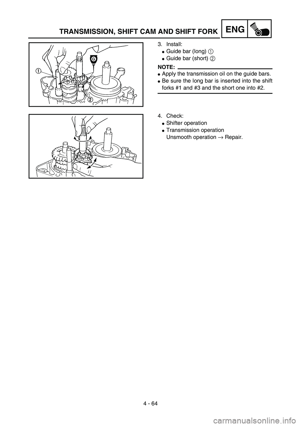
3. Install:
�Guide bar (long) 1
�Guide bar (short) 2
NOTE:
�Apply the transmission oil on the guide bars.
�Be sure the long bar is inserted into the shift
forks #1 and #3 and the short one into #2.
5PA41960
4. Check:
�Shifter operation
�Transmission operation
Unsmooth operation → Repair.
5PA41970
TRANSMISSION, SHIFT CAM AND SHIFT FORK
Page 396 of 508

5 - 35
CHAS
13. Check:
�Inner tube smooth movement
Tightness/binding/rough spots → Repeat
the steps 2 to 12.
5PA51080
14. Compress the front fork fully.
15. Fill:
�Front fork oil
Until outer tube top surface with recom-
mended fork oil 1.
CAUTION:
�Be sure to use recommended fork oil. If
other oils are used, they may have an
excessively adverse effect on the front
fork performance.
�Never allow foreign materials to enter the
front fork.
Recommended oil:
Suspension oil “01”
5PA51090
16. After filling, pump the damper rod 1 slowly
up and down more than 10 times to distrib-
ute the fork oil.
17. Fill:
�Front fork oil
Until outer tube top surface with recom-
mended fork oil once more.
5PA51100
18. After filling, pump the outer tube 1 slowly
up and down (about 150 mm (5.9 in)
stroke) to distribute the fork oil once more.
NOTE:
Be careful not to excessive full stroke. A stroke
of 150 mm (5.9 in) or more will cause air to
enter. In this case, repeat the steps 15 to 18.
5PA51110
FRONT FORK
Page 398 of 508

5 - 36
CHAS
19. Wait ten minutes until the air bubbles have
been removed from the front fork, and the
oil has dispense evenly in system before
setting recommended oil level.
NOTE:
Fill with the fork oil up to the top end of the
outer tube, or the fork oil will not spread over to
every part of the front forks, thus making it
impossible to obtain the correct level.
Be sure to fill with the fork oil up to the top of
the outer tube and bleed the front forks.
20. Measure:
�Oil level (left and right) a
Out of specification → Adjust.
NOTE:
Be sure to install the spring guide 2 when
checking the oil level.
WARNING
Never fail to make the oil level adjustment
between the maximum and minimum level
and always adjust each front fork to the
same setting. Uneven adjustment can
cause poor handling and loss of stability.
Standard oil level:
90 mm (3.54 in)
Extent of adjustment:
80 ~ 120 mm (3.15 ~ 4.72 in)
From top of outer tube with
inner tube and damper rod 1
fully compressed without
spring.
5PA51120
FRONT FORK
Page 454 of 508
6 - 2
–+ELECIGNITION SYSTEM
EC620000
IGNITION SYSTEM
INSPECTION STEPS
Use the following steps for checking the possibility of the malfunctioning engine being attributable to
ignition system failure and for checking the spark plug which will not spark.
*marked: Only when the ignition checker is used.
NOTE:
�Remove the following parts before inspection.
1) Seat
2) Fuel tank
�Use the following special tools in this inspection.
Dynamic spark tester:
YM-34487
Ignition checker:
90890-06754Pocket tester:
YU-3112-C/90890-03112
Spark gap test*Clean or replace
spark plug.
Check entire ignition
system for connection.Repair or replace.
Check engine stop switch. Replace.
Check ignition coil. Primary coil Replace.
Secondary coil Replace.
Check spark plug cap. Replace.
Check CDI magneto. Pickup coil Replace.
Charging coil Replace.
Replace CDI unit.
No spark
OK
OK
OK
OK
OK
Spark
No good
No good
No good
No good
No good
No good
No good
Page 462 of 508
6 - 5
–+ELECIGNITION SYSTEM
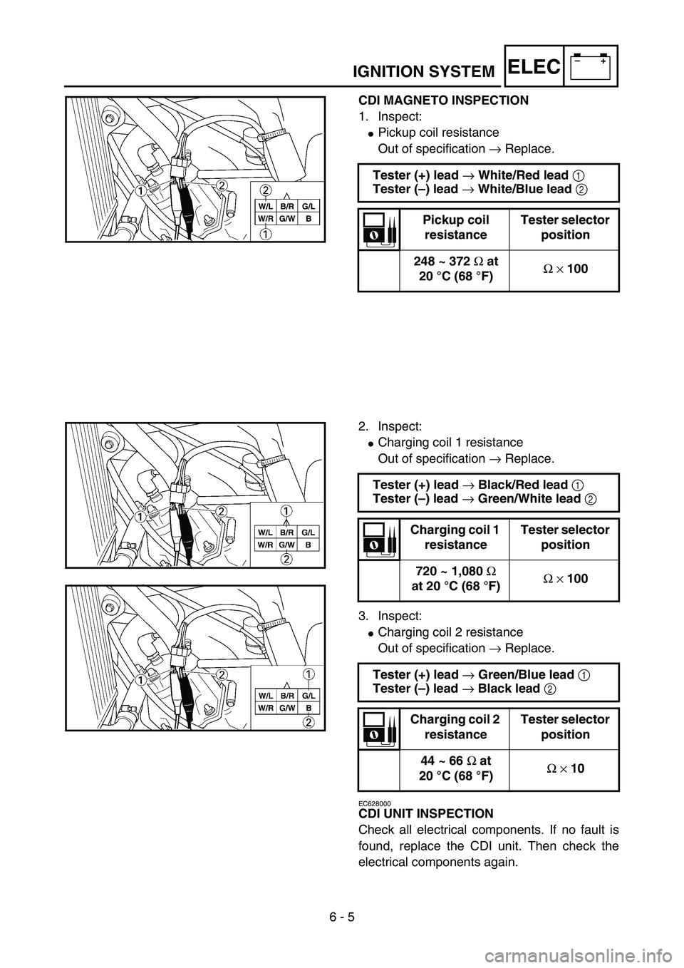
CDI MAGNETO INSPECTION
1. Inspect:
�Pickup coil resistance
Out of specification → Replace.
Tester (+) lead
→ White/Red lead
1
Tester (–) lead
→ White/Blue lead
2
Pickup coil
resistanceTester selector
position
248 ~ 372
Ω at
20 °C (68 °F)Ω
× 100
5PA60080
2. Inspect:
�Charging coil 1 resistance
Out of specification → Replace.
3. Inspect:
�Charging coil 2 resistance
Out of specification → Replace.
EC628000
CDI UNIT INSPECTION
Check all electrical components. If no fault is
found, replace the CDI unit. Then check the
electrical components again.Tester (+) lead
→ Black/Red lead
1
Tester (–) lead
→ Green/White lead
2
Charging coil 1
resistanceTester selector
position
720 ~ 1,080
Ω
at 20 °C (68 °F)Ω
× 100
Tester (+) lead
→ Green/Blue lead
1
Tester (–) lead
→ Black lead
2
Charging coil 2
resistanceTester selector
position
44 ~ 66
Ω at
20 °C (68 °F)Ω
× 10
5PA60090
5PA60100
Page 464 of 508

7 - 1
TUN
EC700000
TUNING
EC710000
ENGINE
Carburetor setting
�The role of fuel is to cool the engine, and in
the case of a 2-stroke engine, to lubricate the
engine in addition to power generation.
Accordingly, if a mixture of air and fuel is too
lean, abnormal combustion will occur, and
engine seizure may result. If the mixture is
too rich, spark plugs will get wet with oil, thus
making it impossible to bring the engine into
full play or if the worst comes to the worst,
the engine may stall.
�The richness of the air-fuel mixture required
for the engine will vary with atmospheric con-
ditions of the day and therefore, the settings
of the carburetor must be properly suited to
the atmospheric conditions (air pressure,
humidity and temperature).
�Finally, the rider himself must make a test
run and check his machine for conditions
(pick-up of engine speed, road surface con-
ditions) and for the discoloration of the spark
plug(s).
After taking these into consideration, he must
select the best possible carburetor settings.
* It is advisable to make a note of settings,
atmospheric conditions, road surface condi-
tion, lap-time, etc. so that the memorandum
can be used as a reference useful for future.
Atmospheric conditions and carburetor
settings
The air density (i.e., concentration of oxygen
in the air) determines the richness or lean-
ness of the air/fuel mixture. Therefore, refer
to the above table for mixture settings.
Air temp. HumidityAir
pressure
(altitude)Mixture Setting
High High Low (high) Richer Leaner
Low Low High (low) Leaner Richer
SETTING
Page 466 of 508
7 - 2
TUN
That is:
�Higher temperature expands the air with its
resultant reduced density.
�Higher humidity reduces the amount of oxy-
gen in the air by so much of the water vapor
in the same air.
�Lower atmospheric pressure (at a high alti-
tude) reduces the density of the air.
Test run
After warming up the engine equipped with the
standard type carburetor(s) and spark plug(s),
run two or three laps of the circuit and check
the smooth operation of the engine and discol-
oration of spark plug(s).
ÈNormal
ÉOver burned (too lean)
ÊOil fouled (too rich)
Discoloration Condition of spark plug
NormalInsulator is dry and burnt
brown.
Over burned
(too lean)Insulator is whitish.
Oil fouled
(too rich)Insulator is sooty and wet.
5PA70010
È
É
Ê
SETTING
Page 482 of 508

7 - 9
TUNSETTING
Change of the heat range of spark plugs
Judging from the discoloration of spark plugs,
if they are found improper, it can be corrected
by the following two methods; changing carbu-
retor settings and changing the heat range of
spark plug.
�In principle, it is advisable to first use spark
plugs of standard heat range, and judging
from the discoloration of spark plugs, adjust
carburetor settings.
�If the calibration No. of the main jet must be
changed by ±30, it is advisable to change the
heat range of spark plugs and newly select
the proper main jet.
NOTE:
�When checking the discoloration of spark
plugs, be sure to stop the engine immedi-
ately after a run and check.
�Avoid racing.
�When changing the heat range of spark
plugs, never attempt to change it more than
±1 rank.
�When using a spark plug other than stan-
dard, check its heat range against the stan-
dard and check that it is a resistance type.
�Note that even if the discoloration seems
proper, it may slightly vary with the spark
plug maker and oil in use.Standard spark plugBR10EG/NGK
(resistance type)
5PA70110