Page 81 of 508
 0.9 mm (0.035 in) ----
Advancer type Electrical ----
CDI:
Magneto-model (stat")
SPEC
2 - 14
MAINTENANCE SPECIFICATIONS
EC212300
ELECTRICAL
Item Standard Limit
Ignition system:
Ignition timing (B.T.D.C.) 0.9 mm (0.035 in) ----
Advancer type Electrical ----
CDI:
Magneto-model (stator)/manufac-
turer5PA-00/YAMAHA ----
Charging coil 1 resistance (color) 720 ~ 1,080 Ω at 20 °C (68 °F)
(Green/White – Black/Red)----
Charging coil 2 resistance (color) 44 ~ 66 Ω at 20°C (68 °F)
(Black – Green/Blue)----
Pickup coil resistance (color) 248 ~ 372 Ω at 20°C (68 °F)
(White/Blue – White/Red)----
CDI unit-model/manufacturer 5PA-00/YAMAHA ----
Ignition coil:
Model/manufacturer 5PA-00/YAMAHA ----
Minimum spark gap 6 mm (0.24 in) ----
Primary coil resistance 0.18 ~ 0.28 Ω at 20 °C (68 °F) ----
Secondary coil resistance 6.3 ~ 9.5 kΩ at 20 °C (68 °F) ----
Spark plug cap:
Resistance 4 ~ 6 kΩ at 20 °C (68 °F) ----
Part to be tightened Thread size Q’tyTightening torque
Nm m · kg ft · lb
Stator M6 × 1.0 2 8 0.8 5.8
Rotor M10 × 1.25 1 33 3.3 24
Ignition coil M6 × 1.0 2 7 0.7 5.1
Page 196 of 508
3 - 37
INSP
ADJ
IGNITION TIMING CHECK
IGNITION TIMING CHECK
1. Remove:
�Air scoop
�Spark plug
�Left crankcase cover
2. Attach:
�Dial gauge 1
�Dial gauge stand 2
Dial gauge and stand:
YU-3097/90890-01252
Stand:
YU-12565PA30870
3. Rotate the rotor 1 until the piston reaches
top dead center (TDC). When this hap-
pens, the needle on the dial gauge will stop
and reverse directions even though the
rotor is being turned in the same direction.
4. Set the dial gauge to zero at TDC.
5PA30880
5. From TDC, rotate the rotor clockwise until
the dial gauge indicates that the piston is at
a specified distance from TDC.
Ignition timing (B.T.D.C.):
0.9 mm (0.035 in)
6. Check:
�Ignition timing
Punch mark a on rotor should be aligned
with punch mark b on stator.
Not aligned → Adjust.
5PA30890
Page 198 of 508
3 - 38
INSP
ADJ
IGNITION TIMING CHECK
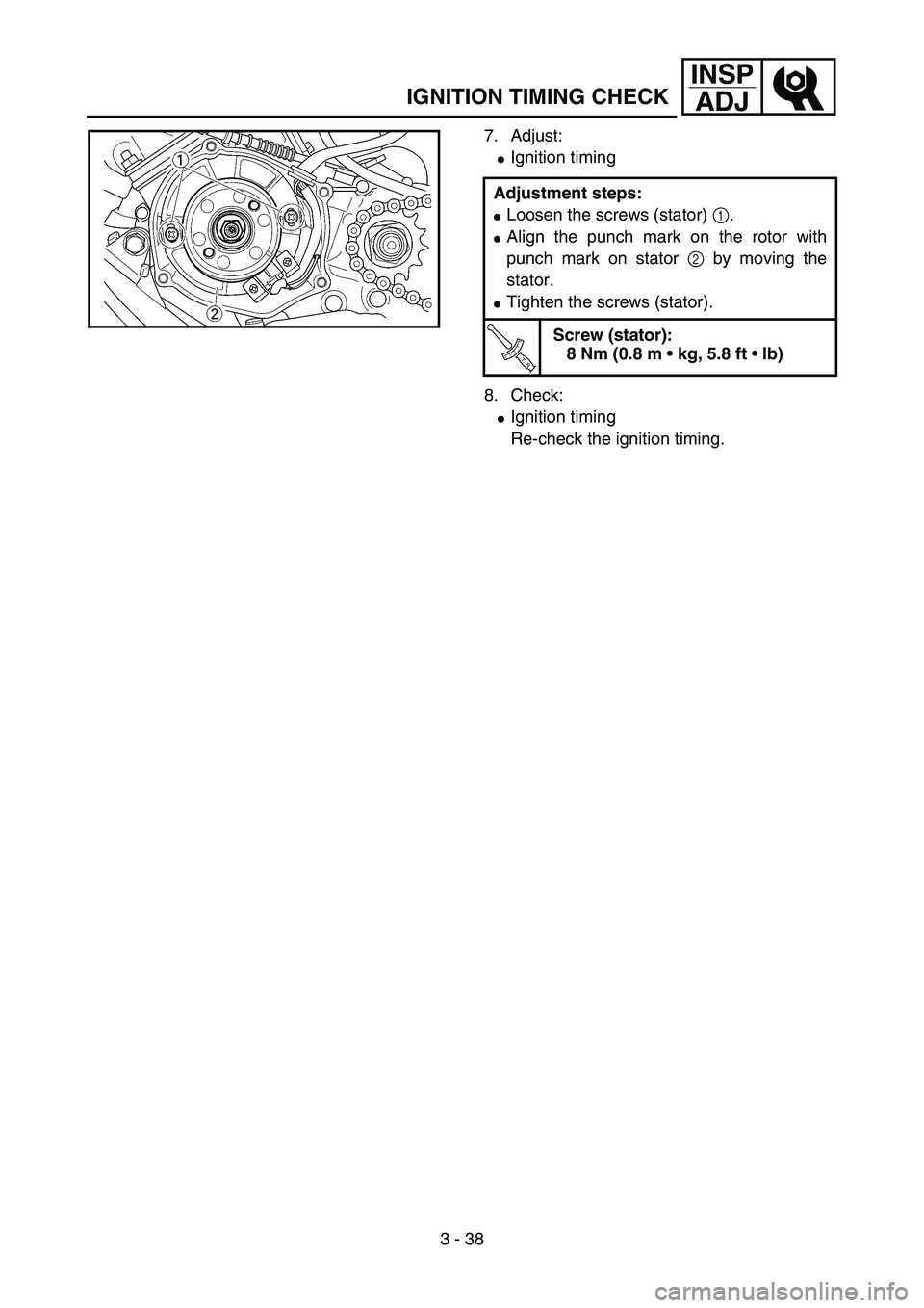
7. Adjust:
�Ignition timing
8. Check:
�Ignition timing
Re-check the ignition timing. Adjustment steps:
�Loosen the screws (stator) 1.
�Align the punch mark on the rotor with
punch mark on stator 2 by moving the
stator.
�Tighten the screws (stator).
T R..
Screw (stator):
8 Nm (0.8 m kg, 5.8 ft lb)
5PA30900
Page 292 of 508
4 - 47
ENG
EC4L5000
ASSEMBLY AND INSTALLATION
CDI magneto
1. Install:
�Stator 1
�Screw (stator) 2
NOTE:
Temporarily tighten the screw (stator) at this
point.5PA41430
2. Install:
�Woodruff key 1
�Rotor 2
NOTE:
�Clean the tapered portions of the crankshaft
and rotor.
�When installing the woodruff key, make sure
that its flat surface a is in parallel with the
crankshaft center line b.
�When installing the rotor, align the keyway c
of the rotor with the woodruff key.
5PA41440
3. Install:
�Washer 1
�Nut (rotor) 2
Use the rotor holding tool 3.
Rotor holding tool:
YU-1235/90890-01235
5PA41450
T R..33 Nm (3.3 m · kg, 24 ft · lb)
4. Adjust:
�Ignition timing
Refer to “IGNITION TIMING CHECK” sec-
tion in the CHAPTER 3.
Ignition timing (B.T.D.C.):
0.9 mm (0.035 in)
CDI MAGNETO
Page 294 of 508
4 - 48
ENG
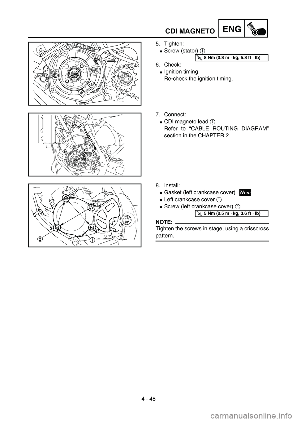
5. Tighten:
�Screw (stator) 1
6. Check:
�Ignition timing
Re-check the ignition timing.
5PA41460
T R..8 Nm (0.8 m · kg, 5.8 ft · lb)
7. Connect:
�CDI magneto lead 1
Refer to “CABLE ROUTING DIAGRAM”
section in the CHAPTER 2.
5PA41470
8. Install:
�Gasket (left crankcase cover)
�Left crankcase cover 1
�Screw (left crankcase cover) 2
NOTE:
Tighten the screws in stage, using a crisscross
pattern.
5PA41480
T R..5 Nm (0.5 m · kg, 3.6 ft · lb)
CDI MAGNETO