Page 148 of 508
3 - 13
INSP
ADJ
TRANSMISSION OIL REPLACEMENT
5. Measure:
�Transmission oil capacity
Out of specification → Adjust.
Oil capacity (periodic oil change):
0.50 L (0.44 Imp qt, 0.52 US qt)
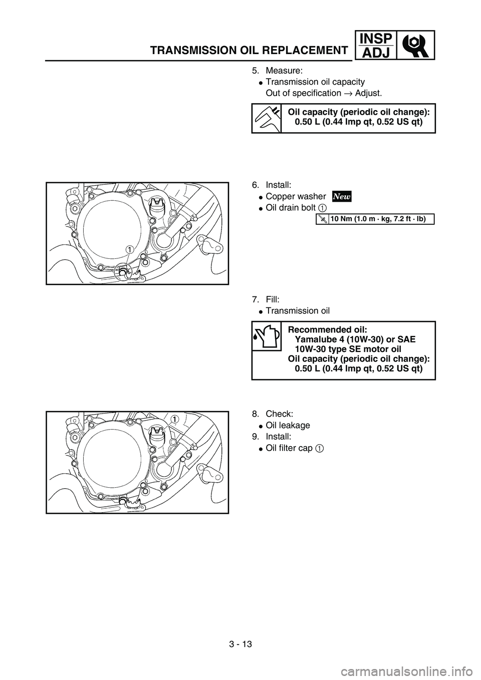
6. Install:
�Copper washer
�Oil drain bolt 1
5PA30210
T R..10 Nm (1.0 m · kg, 7.2 ft · lb)
7. Fill:
�Transmission oil
Recommended oil:
Yamalube 4 (10W-30) or SAE
10W-30 type SE motor oil
Oil capacity (periodic oil change):
0.50 L (0.44 Imp qt, 0.52 US qt)
8. Check:
�Oil leakage
9. Install:
�Oil filter cap 1
5PA30220
Page 168 of 508
3 - 23
INSP
ADJ
DRIVE CHAIN SLACK ADJUSTMENT
4. Check:
�Drive chain stiffness a
Clean and oil the chain and hold as illus-
trated.
Stiff → Replace drive chain.
5PA30520
5. Install:
�Drive chain 1
�Joint 2
�Master link clip 3
CAUTION:
Be sure to install the master link clip to the
direction as shown.
aTurning direction5PA30530
6. Lubricate:
�Drive chain
Drive chain lubricant:
SAE 10W-30 motor oil or suit-
able chain lubricants
5PA30540
EC36A060
DRIVE CHAIN SLACK ADJUSTMENT
1. Elevate the rear wheel by placing the suit-
able stand under the engine.
2. Check:
�Drive chain slack a
In the center between the drive axle and
rear wheel axle.
Out of specification → Adjust.
NOTE:
Before checking and/or adjusting, rotate the
rear wheel through several revolutions and
check the slack several times to find the tight-
est point. Check and/or adjust chain slack with
rear wheel in this “tight chain” position.
Drive chain slack:
35 ~ 45 mm (1.4 ~ 1.8 in)
5PA30550
Page 244 of 508
4 - 23
ENG
NOTE:
When you purchase a cylinder, you cannot
designate its size. Choose the piston that
matches the above chart.
ASSEMBLY AND INSTALLATION
Piston ring and piston
1. Install:
�Piston ring 1
NOTE:
�Take care not to scratch the piston or dam-
age the piston ring.
�Align the piston ring gap with the pin 2.
�After installing the piston ring, check the
smooth movement of it.
5PA40620
2. Install:
�Gasket (cylinder) 1
�Small end bearing 2
�Dowel pin 3
NOTE:
�Apply the engine oil on the bearing (crank-
shaft and connecting rod) and connecting
rod big end washers.
�Install the gasket with the seal print side
toward the crankcase.
5PA40630
CYLINDER HEAD, CYLINDER AND PISTON
Page 246 of 508
4 - 24
ENG
3. Install:
�Piston 1
�Piston pin 2
�Piston pin clip 3
NOTE:
�The arrow a on the piston dome must point
to exhaust side.
�Before installing the piston pin clip, cover the
crankcase with a clean rag to prevent the
piston pin clip from falling into the crankcase
cavity.
CAUTION:
Do not allow the clip open ends to meet the
piston pin slot b.
5PA40640
5PA40650
Cylinder head and cylinder
1. Apply:
�Engine oil
To piston 1, piston ring 2 and cylinder
surface.
2. Install:
�Cylinder 1
CAUTION:
Make sure the piston ring is properly posi-
tioned. Install the cylinder with one hand
while compressing the piston ring with the
other hand.
NOTE:
After installing, check the smooth movement of
the piston.
5PA40660
5PA40670
3. Install:
�Nut (cylinder) 1
NOTE:
Tighten the nuts in stage, using a crisscross
pattern.
5PA40680
T R..28 Nm (2.8 m · kg, 20 ft · lb)
CYLINDER HEAD, CYLINDER AND PISTON
Page 272 of 508
4 - 37
ENG
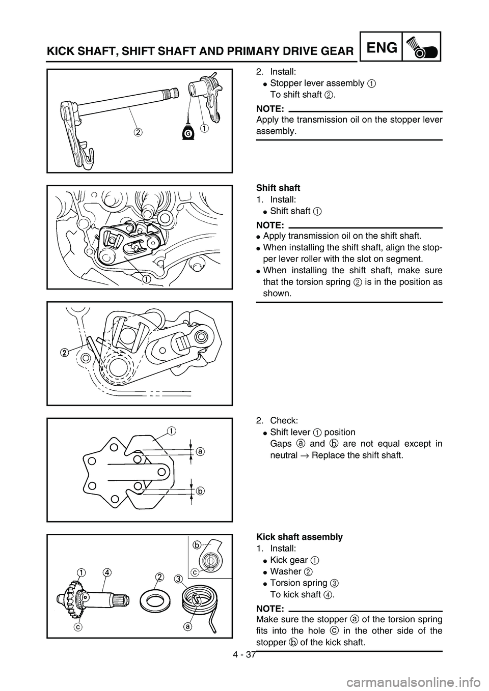
2. Install:
�Stopper lever assembly 1
To shift shaft 2.
NOTE:
Apply the transmission oil on the stopper lever
assembly.
5PA41070
Shift shaft
1. Install:
�Shift shaft 1
NOTE:
�Apply transmission oil on the shift shaft.
�When installing the shift shaft, align the stop-
per lever roller with the slot on segment.
�When installing the shift shaft, make sure
that the torsion spring 2 is in the position as
shown.
5PA41080
5PA41090
2. Check:
�Shift lever 1 position
Gaps a and b are not equal except in
neutral → Replace the shift shaft.
5PA41100
Kick shaft assembly
1. Install:
�Kick gear 1
�Washer 2
�Torsion spring 3
To kick shaft 4.
NOTE:
Make sure the stopper a of the torsion spring
fits into the hole c in the other side of the
stopper b of the kick shaft.
5PA41110
KICK SHAFT, SHIFT SHAFT AND PRIMARY DRIVE GEAR
Page 312 of 508

4 - 57
ENG
Crankshaft
1. Install:
�Crankshaft 1
Use the crankshaft installing tool 2, 3, 4.
ÈFor USA and CDN
ÉExcept for USA and CDN
NOTE:
�Hold the connecting rod at top dead center
with one hand while turning the nut of the
installing tool with the other. Operate the
installing tool until the crankshaft bottoms
against the bearing.
�Before installing the crankshaft, clean the
contacting surface of crankcase.
�Apply the lithium soap base grease on the oil
seal lip.
CAUTION:
Do not use a hammer to drive in the crank-
shaft.
Crankshaft installing pot 2:
YU-90050/90890-01274
Crankshaft installing bolt 3:
YU-90050/90890-01275
Adapter (M10) 4:
YM-1277/90890-01277
5PA41720
ÈÉ
5PA41730
2. Check:
�Shifter operation
�Transmission operation
Unsmooth operation → Repair.
3. Apply:
�Sealant
On the right crankcase 1.
NOTE:
Clean the contacting surface of left and right
crankcase before applying the sealant.
Quick gasket®:
ACC-QUICK-GS-KT
YAMAHA Bond No. 1215:
90890-85505
5PA41740
5PA41750
CRANKCASE AND CRANKSHAFT
Page 314 of 508
4 - 58
ENG
4. Install:
�Dowel pin 1
�Right crankcase 2
To left crankcase 3.
NOTE:
�Turn the shift cam 4 to the position shown in
the figure so that it does not contact the
crankcase when installing the crankcase.
�Fit the right crankcase onto the left crank-
case. Tap lightly on the case with soft ham-
mer.
�When installing the crankcase, the connect-
ing rod should be positioned at TDC (top
dead center).
5PA41760
5PA41770
5. Install:
�Clamp 1
�Screw (crankcase) 2
NOTE:
Tighten the crankcase tightening screws in
stage, using a crisscross pattern.
5PA41780
T R..8 Nm (0.8 m · kg, 5.8 ft · lb)
6. Install:
�Crankcase oil seal holder 1
�Bolt (crankcase oil seal holder) 2
7. Remove:
�Sealant
Forced out on the cylinder mating surface.
8. Apply:
�Engine oil
To the crank pin, bearing, oil delivery hole
and connecting rod end washer.
9. Check:
�Crankshaft and transmission operation
Unsmooth operation → Repair.
5PAR0010
T R..20 Nm (2.0 m · kg, 14 ft · lb)
CRANKCASE AND CRANKSHAFT
Page 320 of 508
4 - 61
ENG
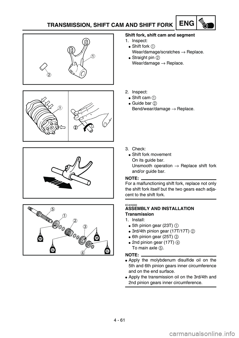
Shift fork, shift cam and segment
1. Inspect:
�Shift fork 1
Wear/damage/scratches → Replace.
�Straight pin 2
Wear/damage → Replace.
5PA41840
2. Inspect:
�Shift cam 1
�Guide bar 2
Bend/wear/damage → Replace.
5PA41850
3. Check:
�Shift fork movement
On its guide bar.
Unsmooth operation → Replace shift fork
and/or guide bar.
NOTE:
For a malfunctioning shift fork, replace not only
the shift fork itself but the two gears each adja-
cent to the shift fork.5PA41860
EC4H5000
ASSEMBLY AND INSTALLATION
Transmission
1. Install:
�5th pinion gear (23T) 1
�3rd/4th pinion gear (17T/17T) 2
�6th pinion gear (25T) 3
�2nd pinion gear (17T) 4
To main axle 5.
NOTE:
�Apply the molybdenum disulfide oil on the
5th and 6th pinion gears inner circumference
and on the end surface.
�Apply the transmission oil on the 3rd/4th and
2nd pinion gears inner circumference.
5PA41870
TRANSMISSION, SHIFT CAM AND SHIFT FORK