Page 19 of 336

19
OPERATION OF INSTRUMENTS AND
CONTROLS
Keys and Doors
Keys20
. . . . . . . . . . . . . . . . . . . . . . . . . . . . . . . . . . . . .\
. . . . . . . . . . . . . . . . . .
Hybrid vehicle immobilizer system 21
. . . . . . . . . . . . . . . . . . . . . . . . . . . . .
Smart entry and start system 24
. . . . . . . . . . . . . . . . . . . . . . . . . . . . . . . . . .
Wireless remote control 34
. . . . . . . . . . . . . . . . . . . . . . . . . . . . . . . . . . . . \
. .
Side doors 39
. . . . . . . . . . . . . . . . . . . . . . . . . . . . . . . . . . . . \
. . . . . . . . . . . . .
Back door 41
. . . . . . . . . . . . . . . . . . . . . . . . . . . . . . . . . . . . \
. . . . . . . . . . . . . . .
Power windows 42
. . . . . . . . . . . . . . . . . . . . . . . . . . . . . . . . . . . . \
. . . . . . . . . .
Hood 44
. . . . . . . . . . . . . . . . . . . . . . . . . . . . . . . . . . . . \
. . . . . . . . . . . . . . . . . . .
Theft deterrent system 45
. . . . . . . . . . . . . . . . . . . . . . . . . . . . . . . . . . . . \
. . .
Fuel tank cap 47
. . . . . . . . . . . . . . . . . . . . . . . . . . . . . . . . . . . . \
. . . . . . . . . . .
SECTION 2– 1
Page 47 of 336

47
CANCELLING THE SYSTEM
The system will be cancelled by the
above mentioned two ways.
If the tail lights come on for 2 seconds,
the theft deterrent system has been
alarmed. Check to see if there is any
abnormality on your vehicle.
TESTING THE SYSTEM1. Open all the windows.
2. Set the system as described above. The doors should be locked with the
mechanical key, wireless remote control
transmitter or smart function. Be sure
to wait until the indicator light goes off
or starts flashing.
3. Unlock any door from the inside. The system s hould activate the alarm.
4. Stop the alarm as described above.
5. Repeat this operation for the other doors and hood. When testing the back
door, also check that the system is
activated when the auxiliary battery ter-
minal is disconnected and then recon-
nected. When testing the hood, release
the lock with the hood lock release
lever and raise the hood.
If the system does not work properly,
have it checked by your Toyota dealer.
21p117
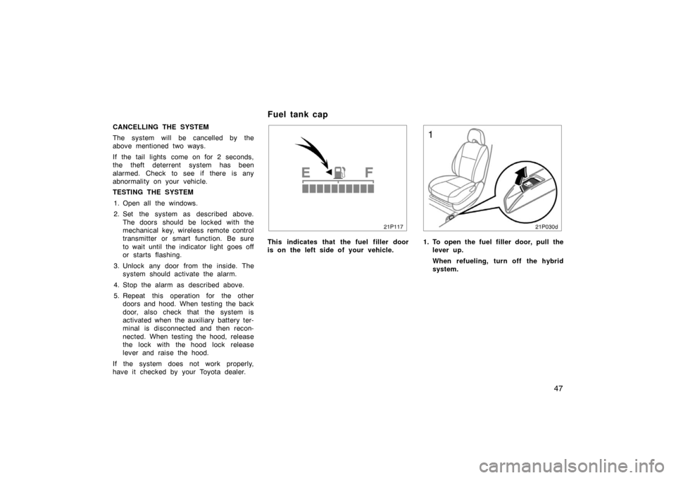
This indicates that the fuel filler door
is on the left side of your vehicle.
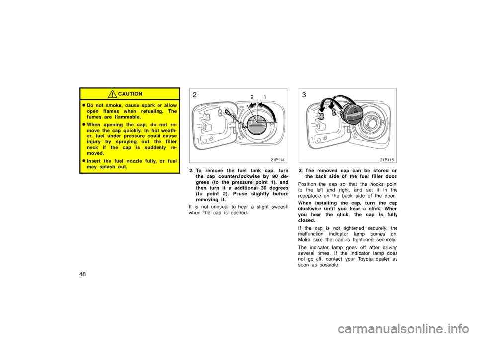
21p030d
1. To open the fuel filler door, pull the lever up.
When refueling, turn off the hybrid
system.
Fuel tank cap
Page 48 of 336

48
CAUTION
�Do not smoke, cause spark or allow
open flames when refueling. The
fumes are flammable.
�When opening the cap, do not re-
move the cap quickly. In hot weath-
er, fuel under pressure could cause
injury by spraying out the filler
neck if the cap is suddenly re-
moved.
�Insert the fuel nozzle fully, or fuel
may splash out.
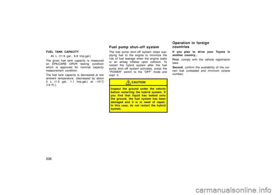
21p114
12
2. To remove the fuel tank cap, turnthe cap counterclockwise by 90 de-
grees (to the pressure point 1), and
then turn it a additional 30 degrees
(to point 2). Pause slightly before
removing it.
It is not unusual to hear a slight swoosh
when the cap is opened.
21p115
3. The removed cap can be stored on the back side of the fuel filler door.
Position the cap so that the hooks point
to the left and right, and set it in the
receptacle on the back side of the door.
When installing the cap, turn the cap
clockwise until you hear a click. When
you hear the click, the cap is fully
closed.
If the cap is not tightened securely, the
malfunction indicator lamp comes on.
Make sure the cap is tightened securely.
The indicator lamp goes off after driving
several times. If the indicator lamp does
not go off, contact your Toyota dealer as
soon as possible.
Page 49 of 336
49
CAUTION
�Make sure the cap is installed se-
curely to prevent fuel spillage in
the event of an accident.
�Use only a genuine Toyota fuel tank
cap for replacement. It is designed
to regulate fuel tank pressure.
NOTICE
To prevent damage to the cap, apply
force only in the turning direction to
the cap. Do not pull or pry it.
Page 150 of 336
150
Information
26p009b
Type AType B
Push the “INFO” button to display the
“Information Menu” screen.
26p027c
Trip information: The energy monitor and
fuel consumption screen are selected.
Language: Select language screen is
shown.
Screen setting: The screen setting screen
is shown.
—Trip information
26p038d
Energy monitor screen
Touch the “Energy” switch. Vehicle driving
condition, hybrid system operating condi-
tion and energy recovery condition are
shown.
1. Indicates the flow of energy by orange
and yellow arrows. While the energy is
recovered, the arrows change the
pointing direction and turn green.
2. Indicates the remaining capacity of the
hybrid vehicle battery.
The screen display updates every 3 sec-
onds, so it may not coincide with the
actual status.
Page 206 of 336

206
FUEL TANK CAPACITY45 L (11.9 gal., 9.9 lmp.gal.)
The given fuel tank capacity is measured
on EPA/CARB ORVR testing condition
which is approved for nominal capacity
measurement condition.
The fuel tank capacity is decreased at low
ambient temperature. (decreased by about
5 L (1.3 gal., 1.1 lmp.gal.) at −10 �C
(14 �F).)
Fuel pump shut�off system
The fuel pump shut −off system stops sup-
plying fuel to the engine to minimize the
risk of fuel leakage when the engine stalls
or an airbag inflates upon collision. To
restart the hybrid system after the fuel
pump shut −off system activates, press the
“POWER” switch to the “OFF” mode and
start it.
CAUTION
Inspect the ground under the vehicle
before restarting the hybrid system. If
you find that liquid has leaked onto
the ground, the fuel system has been
damaged and it is in need of repair.
In this case, do not restart the hybrid
system.
If you plan to drive your Toyota in
another country...
First , comply with the vehicle registration
laws.
Second, confirm the availability of the cor-
rect fuel (unleaded and minimum octane
number).
Operation in foreign
countries
Page 225 of 336

225
Ti r e relat ed ter m
Meaning
Cold tire inflation pressuretire inflation pressure when the vehicl
e has been parked at least 3 hours or
more, or it has not been driven more t han 1.5 km or 1 mile under that condition
Maximum inflation pressurethe maximum cold inflation pressure to which a tire may be inflated and shown
on the sidewall of the tire
Recommended inflation pressurecold tire inflation pressure recommended by a manufacturer
Accessory weight
the combined weight (in excess of those standard items which may be replaced)
of automatic transmission, power steering, power brakes, power windows, pow-
er seats, radio, and heater, to the extent that these items are available as
factory−installed equipment (whether installed or not)
Curb weight
the weight of a motor vehicle with standard equipment including the maximum
capacity of fuel, oil, and coolant, and, if so equipped, air conditioning and addi-
tional weight optional engine
Maximum loaded vehicle weight
t he sum of —
(a) curb weight;
(b) accessory weight;
(c) vehicle capacity weight; and
(d) production options weight
Normal occupant weight68 kg (150 lb.) times the number of occupants specified in the second column
of Table 1 that follows
—Glossary of tire terminology
Page 228 of 336

228 Vehicle load limits include total load
capacity, seating capacity, towing ca-
pacity and cargo capacity. Follow the
load limits shown below.
Total load capacity:
379 kg (835 lb.)
Total load capacity means combined
weight of occupants, cargo and lug-
gage.
Seating capacity: Total 5 (Front 2, Rear 3)
Seating capacity means the maximum
number of occupants whose esti-
mated average weight is 68 kg (150
lb.) per person. Depending on the
weight of each person, the seating ca-
pacity given may exceed the total
load capacity.
NOTICE
Even if the number of occupants
are within the seating capacity,
do not exceed the total load ca-
pacity.
Towing capacity
Toyota does not recommend towing
a trailer with your vehicle. Your ve-
hicle is not designed for trailer towing.
Cargo capacity
Cargo capacity may increase or de-
crease depending on the size (weight)
and the number of occupants. For de-
tails, see “Capacity and distribution”
that follows.
CAUTION
Do not apply the load more than
each load limit. That may cause
not only damage to the tires, but
also deterioration to the steering
ability and braking ability, which
may cause an accident.
When stowing cargo and luggage in
the vehicle, observe the following:� Put cargo and luggage in the lug-
gage compartment when at all
possible. Be sure all items are se-
cured in place.
� Be careful to keep the vehicle bal-
anced. Locating the weight as far
forward as possible helps maintain
balance.
� For better fuel economy, do not
carry unneeded weight.
CAUTION
�To prevent cargo and l uggage
from sliding forward during
braking, do not stack anything
in the luggage compartment.
Keep cargo and luggage low,
as close to the floor as pos-
sible.
Vehicle load limits Cargo and luggage—
—Stowage precautions