Page 898 of 5135

F45141
Skid Control ECU
with Actuator
12
S1
VCM 11
PMC
27E2
S1
S1
STP 37
S1
Battery FL MAIN O1
Oil Pressure Sensor
1
Y±G
1
4B
1
2 2
*1: 1AZ±FSE
*2: 1CD±FTV3
12 33ALT Engine Room R/B No.3
B (*2)
B±G (*1)1
4D Engine Room J/B No.4B±G (*1)
B±L (*2) W (*2) R±W (*3)1 2Y±R
GR
R±W (*4)R±W (*3)
R±W (*4)
11 1 2 2
22DL DA
DA DNDM IR1
6
IE3
11
IE3
2
IR1
ED1 1Driver Side J/B
S13 Stop Light SW
G±W (*3)G±W (*3)G±W (*4) G±W (*4) G±W
To
Stop
Light
B±G (*1)
STOP
*3: LHD
*4: RHDALT 05±812
± DIAGNOSTICSABS WITH EBD & BA & TRC & VSC SYSTEM
AVENSIS REPAIR MANUAL (RM1018E)
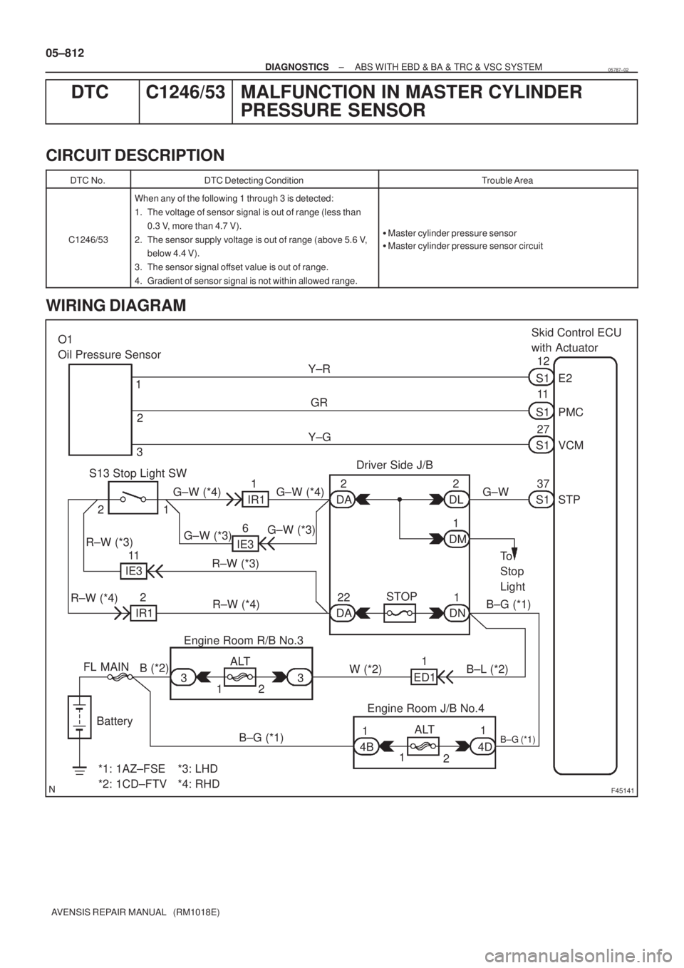
DTC C1246/53 MALFUNCTION IN MASTER CYLINDER
PRESSURE SENSOR
CIRCUIT DESCRIPTION
DTC No.DTC Detecting ConditionTrouble Area
C1246/53
When any of the following 1 through 3 is detected:
1. The voltage of sensor signal is out of range (less than
0.3 V, more than 4.7 V).
2. The sensor supply voltage is out of range (above 5.6 V,
below 4.4 V).
3. The sensor signal offset value is out of range.
4. Gradient of sensor signal is not within allowed range.
�Master cylinder pressure sensor
�Master cylinder pressure sensor circuit
WIRING DIAGRAM
05787±02
Page 899 of 5135

±
DIAGNOSTICS ABS WITH EBD & BA & TRC & VSC SYSTEM
05±813
AVENSIS REPAIR MANUAL (RM1018E)
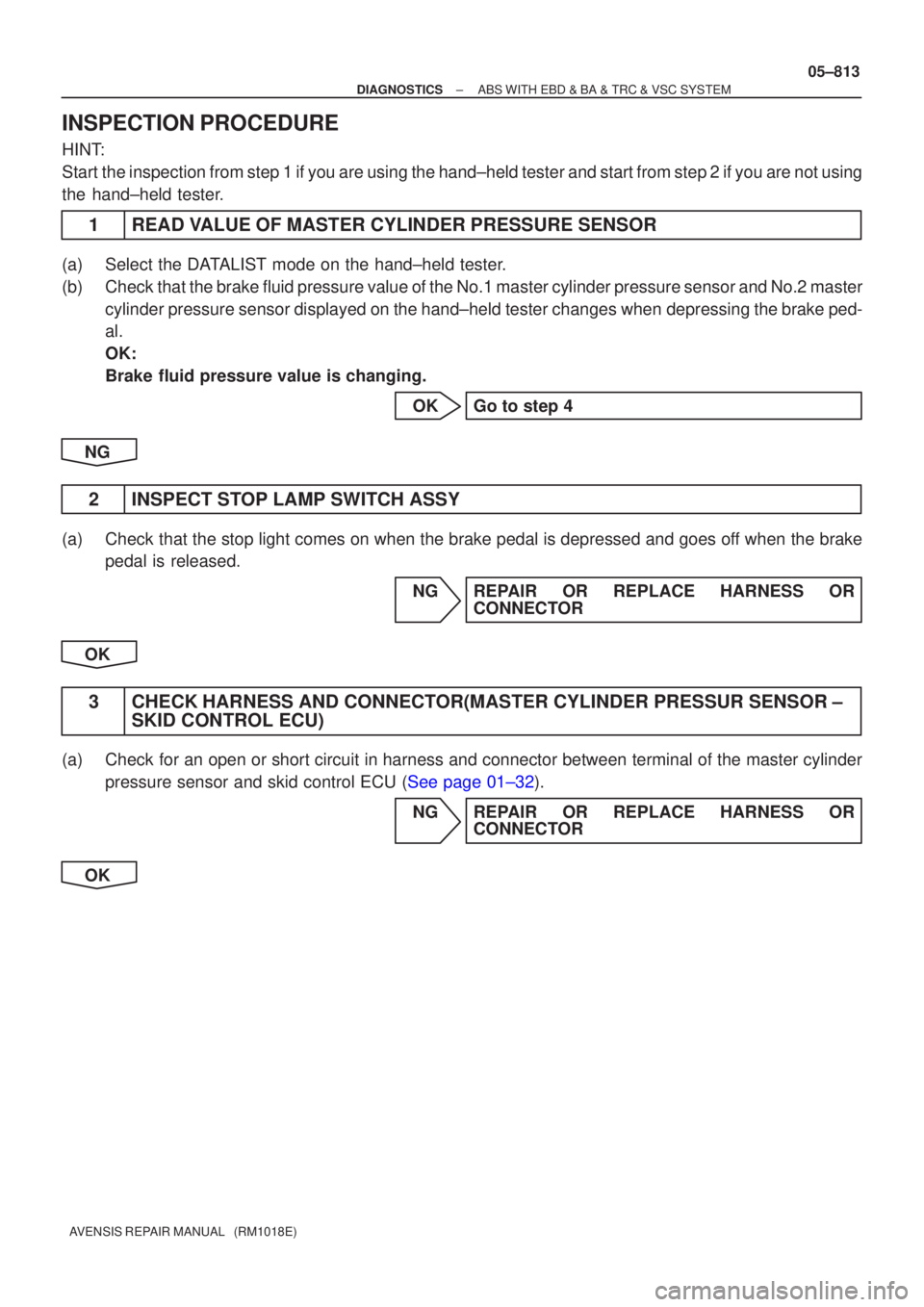
INSPECTION PROCEDURE
HINT:
Start the inspection from step 1 if you are using the hand±held tester and\
start from step 2 if you are not using
the hand±held tester.
1READ VALUE OF MASTER CYLINDER PRESSURE SENSOR
(a)Select the DATALIST mode on the hand±held tester.
(b)Check that the brake fluid pressure value of the No.1 master cylinder pressur\
e sensor and No.2 master
cylinder pressure sensor displayed on the hand±held tester changes wh\
en depressing the brake ped-
al.
OK:
Brake fluid pressure value is changing.
OKGo to step 4
NG
2INSPECT STOP LAMP SWITCH ASSY
(a)Check that the stop light comes on when the brake pedal is depressed and goes\
off when the brake pedal is released.
NGREPAIR OR REPLACE HARNESS ORCONNECTOR
OK
3CHECK HARNESS AND CONNECTOR(MASTER CYLINDER PRESSUR SENSOR ± SKID CONTROL ECU)
(a)Check for an open or short circuit in harness and connector between terminal \
of the master cylinder
pressure sensor and skid control ECU (See page 01±32).
NG REPAIR OR REPLACE HARNESS ORCONNECTOR
OK
Page 900 of 5135
C94397STP
05±814
±
DIAGNOSTICS ABS WITH EBD & BA & TRC & VSC SYSTEM
AVENSIS REPAIR MANUAL (RM1018E)
4INSPECT SKID CONTROL ECU TERMINAL VOLTAGE(STP TERMINAL)
(a)Disconnect the skid control ECU connector.
(b)Measure the voltage between terminal STP of the skid control ECU harness side connector and body ground
when the brake pedal is depressed.
OK:
Voltage: 8 to 14 V
NGREPAIR OR REPLACE HARNESS OR CONNECTOR
OK
REPLACE ABS & TRACTION ACTUATOR ASSY(See page 32±57)
Page 901 of 5135
05±808
± DIAGNOSTICSABS WITH EBD & BA & TRC & VSC SYSTEM
AVENSIS REPAIR MANUAL (RM1018E)
DTC C1241/41 LOW BATTERY POSITIVE VOLTAGE OR
ABNORMALLY HIGH BATTERY POSITIVE
VOLTAGE
CIRCUIT DESCRIPTION
DTC No.DTC Detecting ConditionTrouble Area
C1241/41
Low battery voltage is less than 9.8 V at the time of non±
operation of ABS control or less than 9.4 V at the time of
operation of ABS control, or battery voltage is more than
17.4 V.�Battery
�IC regulator
�Power source circuit
05436±04
Page 902 of 5135
F45133
1 2 33ALT Engine Room R/B No.3
B (*2) W (*2) B±G (*1)
ALT 1
4D 1
1
4B Engine Room J/B No.4 ED1
BatteryFL MAIN
*1: 1AZ±FSE
*2: 1CD±FTV
*3: LHD
*4: RHD B±G (*1)
B±L (*2)
1
5918
1 53
2
1
DH DA DB DN
DH
AM1 ECU±IG IG Relay
W±BS110
GND1 GND2
S16
W±BW±B
EA W±B
IJ B (*2) B±G (*1)G±Y R±W
W±B
G±R G±Y G±YR±W R±W
R±W J/C
J10 J20 J10 J20 S1 IG1GC GC 1422
IE1Skid Control ECU
with Actuator
(*3) (*4) (*3) (*4)
I13
Ignition SW
1 3
B±L (*2)
Driver Side J/B
AM1 IG1
± DIAGNOSTICSABS WITH EBD & BA & TRC & VSC SYSTEM
05±809
AVENSIS REPAIR MANUAL (RM1018E)
WIRING DIAGRAM
Page 903 of 5135
F45090
Driver Side J/BECU±IG
C94397
GND
IG1
05±810
±
DIAGNOSTICS ABS WITH EBD & BA & TRC & VSC SYSTEM
AVENSIS REPAIR MANUAL (RM1018E)
INSPECTION PROCEDURE
1INSPECT FUSE(ECU±IG FUSE)
(a)Remove the ECU±IG fuse from the driver side J/B.
(b)Check continuity of the ECU±IG fuse. OK:
Continuity
NGINSPECT FOR SHORT CIRCUIT IN ALL HARNESS AND COMPONENTS CONNECTED
TO ECU±IG FUSE
OK
2INSPECT BATTERY
OK:
Voltage: 10 to 14 V NGINSPECT CHARGING SYSTEM
OK
3INSPECT SKID CONTROL ECU TERMINAL VOLTAGE(IG1 TERMINAL)
IN CASE OF USING HAND±HELD TESTER:
(a)Check the voltage condition, which is output from the ECU and displayed \
on the hand±held tester. OK:
ºNormalº is displayed. IN CASE OF NOT USING HAND±HELD TESTER:
(a)Disconnect the skid control connector.
(b)Turn the ignition switch ON.
(c)Measure the voltage between terminals IG1 and GND ofthe skid control ECU harness side connector.
OK:
Voltage: 10 to 14 V
OKREPLACE ABS & TRACTION ACTUATOR ASSY (See page 32±57)
NG
Page 904 of 5135
C94397
GND
±
DIAGNOSTICS ABS WITH EBD & BA & TRC & VSC SYSTEM
05±811
AVENSIS REPAIR MANUAL (RM1018E)
4INSPECT SKID CONTROL ECU CONNECTOR(GND TERMINAL CONTINUITY)
(a)Disconnect the skid control ECU connector.
(b)Measure resistance between terminal GND of the skid
control ECU harness side connector and body ground.
OK:
Resistance: 1 � or less
NGREPAIR OR REPLACE HARNESS OR CONNECTOR(GND TERMINAL ± BODY
GROUND)(See page 01±32)
OK
CHECK AND REPAIR HARNESS AND CONNECTOR(BATTERY ± IG1 TERMINAL)
(See page 01±32)
Page 905 of 5135
![TOYOTA AVENSIS 2005 Service Repair Manual D26540
T4
Turbine Speed SensorECM
NT+ E1227
B±O
2
B
NT± E1235 1 05±884
± DIAGNOSTICSELECTRONIC CONTROLLED AUTOMATIC
TRANSAXLE [ECT] (U241E(1AZ±FE))
AVENSIS REPAIR MANUAL (RM1018E)
DTC P0717/37 TOYOTA AVENSIS 2005 Service Repair Manual D26540
T4
Turbine Speed SensorECM
NT+ E1227
B±O
2
B
NT± E1235 1 05±884
± DIAGNOSTICSELECTRONIC CONTROLLED AUTOMATIC
TRANSAXLE [ECT] (U241E(1AZ±FE))
AVENSIS REPAIR MANUAL (RM1018E)
DTC P0717/37](/manual-img/14/57441/w960_57441-904.png)
D26540
T4
Turbine Speed SensorECM
NT+ E1227
B±O
2
B
NT± E1235 1 05±884
± DIAGNOSTICSELECTRONIC CONTROLLED AUTOMATIC
TRANSAXLE [ECT] (U241E(1AZ±FE))
AVENSIS REPAIR MANUAL (RM1018E)
DTC P0717/37 TURBINE SPEED SENSOR CIRCUIT NO
SIGNAL
CIRCUIT DESCRIPTION
This sensor detects the rotation speed of the input turbine. By comparing the input turbine speed signal (NT)
with the counter gear speed sensor signal (NC), the ECM detects the shift timing of the gears and appropri-
ately controls the engine torque and hydraulic pressure according to various conditions. Thus smooth gear
shifting is performed.
DTC No.DTC Detection ConditionTrouble Area
P0717/37
ECM detects conditions (a), (b), (c) and (d) continuity for 5 sec.
or more: (2 trip detection logic)
(a) Vehicle speed: 50 km/h (20 mph) or more
(b) 2nd, 3rd or O/D gear
(c) Solenoid valves and park/neutral position switch are normal
(d) NT < 300 rpm
�Open or short in speed sensor (NT) circuit
�Speed sensor (NT)
�ECM
WIRING DIAGRAM
05C8U±01