Page 1749 of 5135
I36055
E67361
Push inFree
1 2
± DIAGNOSTICSCRUISE CONTROL SYSTEM
05±1725
AVENSIS REPAIR MANUAL (RM1018E)
3 INSPECT COMBINATION METER ASSY
(a) Disconnect the C11 connector from the combination me-
ter.
(b) Measure the resistance according to the value(s) in the
table below.
Standard:
Tester ConnectionSpecified Condition
Terminal 5 (C11) ± Body ground10 k� or higher
NG REPAIR OR REPLACE HARNESS OR
CONNECTOR
OK
REPAIR OR REPLACE COMBINATION METER ASSY
4 INSPECT CLUTCH START SWITCH ASSY
(a) Disconnect the clutch start switch assy connector.
(b) Measure the resistance according to the value(s) in the
table below.
Standard:
Switch conditionTester connectionSpecification
Switch pin free1 ± 210 k� or higher
Switch pin pushed in1 ± 21 � or less
NG INSPECT CLUTCH START SWITCH ASSY
OK
Page 1750 of 5135
05±1726
±
DIAGNOSTICS CRUISE CONTROL SYSTEM
AVENSIS REPAIR MANUAL (RM1018E)
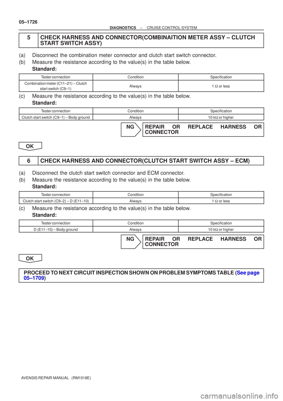
5CHECK HARNESS AND CONNECTOR(COMBINAITION METER ASSY ± CLUTCH START SWITCH ASSY)
(a)Disconnect the combination meter connector and clutch start switch connector.
(b)Measure the resistance according to the value(s) in the table below.
Standard:
Tester connectionConditionSpecification
Combination meter (C11±21) ± Clutch
start switch (C9±1)Always1 � or less
(c)Measure the resistance according to the value(s) in the table below.
Standard:
Tester connectionConditionSpecification
Clutch start switch (C9±1) ± Body groundAlways10 k� or higher
NGREPAIR OR REPLACE HARNESS OR
CONNECTOR
OK
6CHECK HARNESS AND CONNECTOR(CLUTCH START SWITCH ASSY ± ECM)
(a)Disconnect the clutch start switch connector and ECM connector.
(b)Measure the resistance according to the value(s) in the table below. Standard:
Tester connectionConditionSpecification
Clutch start switch (C9±2) ± D (E11±10)Always1 � or less
(c)Measure the resistance according to the value(s) in the table below.
Standard:
Tester connectionConditionSpecification
D (E11±10) ± Body groundAlways10 k� or higher
NGREPAIR OR REPLACE HARNESS OR
CONNECTOR
OK
PROCEED TO NEXT CIRCUIT INSPECTION SHOWN ON PROBLEM SYMPTOMS TABLE (See page
05±1709)
Page 1767 of 5135
I34747
E8E9E12E11 05±1708
± DIAGNOSTICSCRUISE CONTROL SYSTEM
AVENSIS REPAIR MANUAL (RM1018E)
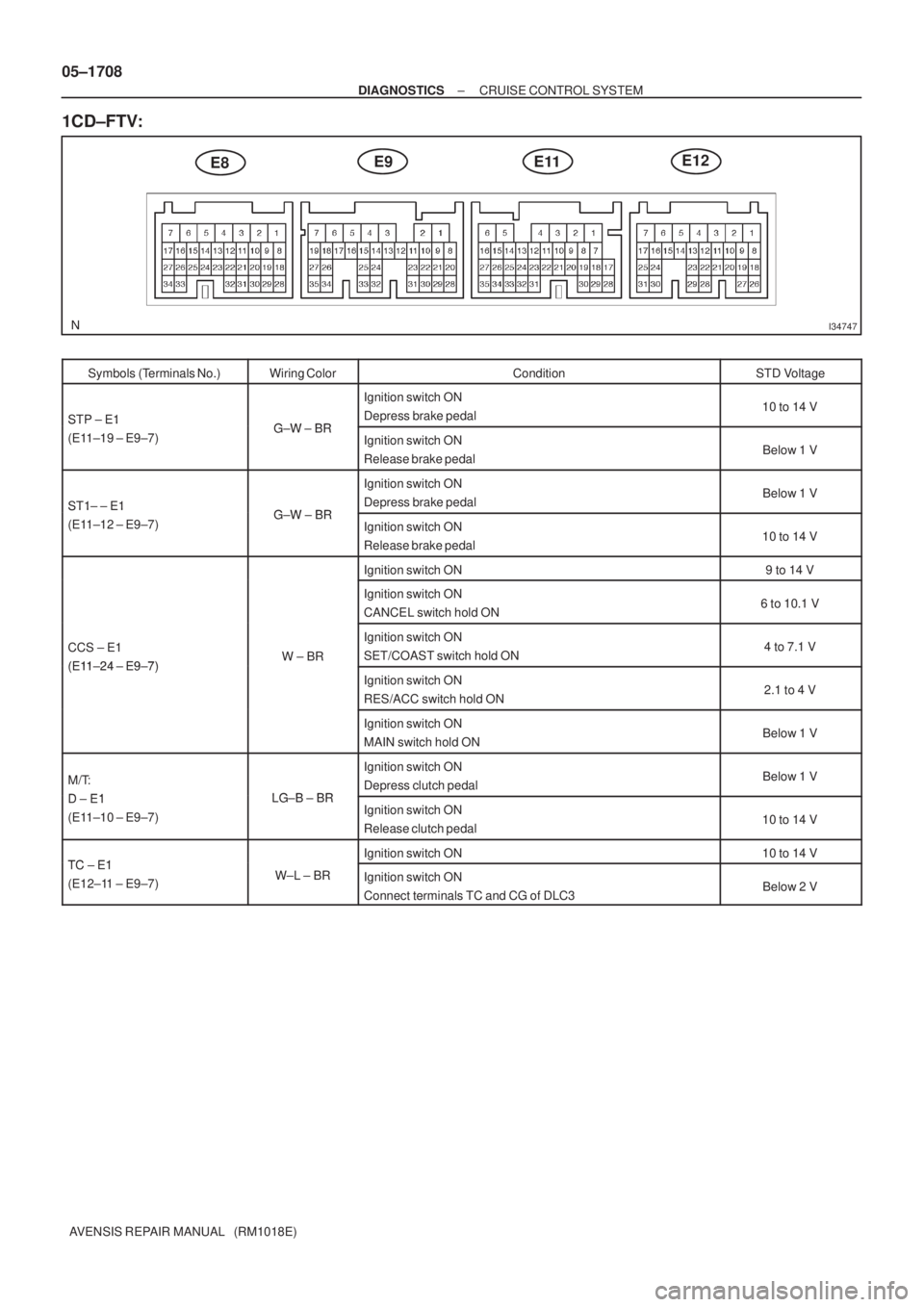
1CD±FTV:
Symbols (Terminals No.)Wiring ColorConditionSTD Voltage
STP ± E1GW BR
Ignition switch ON
Depress brake pedal10 to 14 VSTP E1
(E11±19 ± E9±7)G±W ± BRIgnition switch ON
Release brake pedalBelow 1 V
ST1± ± E1GW BR
Ignition switch ON
Depress brake pedalBelow 1 VST1 E1
(E11±12 ± E9±7)G±W ± BRIgnition switch ON
Release brake pedal10 to 14 V
Ignition switch ON9 to 14 V
Ignition switch ON
CANCEL switch hold ON6 to 10.1 V
CCS ± E1
(E1124 E97)W ± BR
Ignition switch ON
SET/COAST switch hold ON4 to 7.1 V
(E11±24 ± E9±7)Ignition switch ON
RES/ACC switch hold ON2.1 to 4 V
Ignition switch ON
MAIN switch hold ONBelow 1 V
M/T:
DE1LG B BR
Ignition switch ON
Depress clutch pedalBelow 1 V
D ± E1
(E11±10 ± E9±7)LG±B ± BRIgnition switch ON
Release clutch pedal10 to 14 V
TC E1Ignition switch ON10 to 14 VTC ± E1
(E12±11 ± E9±7)W±L ± BRIgnition switch ON
Connect terminals TC and CG of DLC3Below 2 V
Page 1768 of 5135
05ADK±04
I35700
Engine Room J/B No.4
Engine Room R/B
Park/neutral Position Switch (A/T)
LHD:
Combination Meter Assy
Driver Side J/B
DLC3ECM
RHD:
Combination Meter Assy
Cruise Control Main Switch Assy
Stop Lamp Switch Assy Clutch Start Switch Assy (M/T) ECM
DLC3
Driver Side J/B
05±1706
± DIAGNOSTICSCRUISE CONTROL SYSTEM
AVENSIS REPAIR MANUAL (RM1018E)
LOCATION
Page 1774 of 5135
I35838
(1)
(3)
I35840
(3)(1)
I35839
(3)
(1) 05±1704
± DIAGNOSTICSCRUISE CONTROL SYSTEM
AVENSIS REPAIR MANUAL (RM1018E)
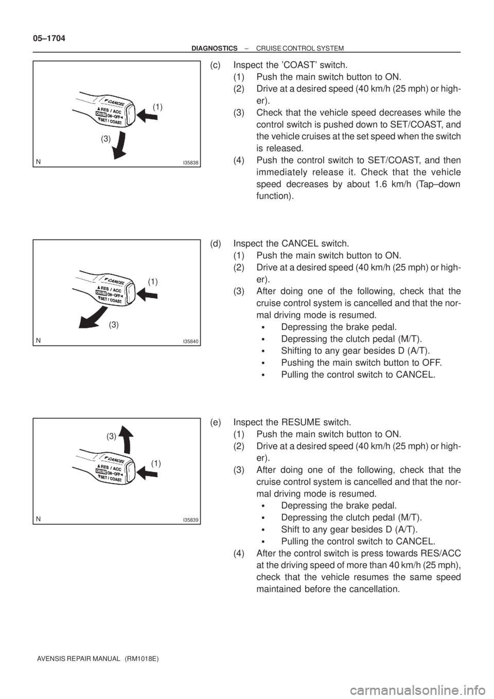
(c) Inspect the 'COAST' switch.
(1) Push the main switch button to ON.
(2) Drive at a desired speed (40 km/h (25 mph) or high-
er).
(3) Check that the vehicle speed decreases while the
control switch is pushed down to SET/COAST, and
the vehicle cruises at the set speed when the switch
is released.
(4) Push the control switch to SET/COAST, and then
immediately release it. Check that the vehicle
speed decreases by about 1.6 km/h (Tap±down
function).
(d) Inspect the CANCEL switch.
(1) Push the main switch button to ON.
(2) Drive at a desired speed (40 km/h (25 mph) or high-
er).
(3) After doing one of the following, check that the
cruise control system is cancelled and that the nor-
mal driving mode is resumed.
�Depressing the brake pedal.
�Depressing the clutch pedal (M/T).
�Shifting to any gear besides D (A/T).
�Pushing the main switch button to OFF.
�Pulling the control switch to CANCEL.
(e) Inspect the RESUME switch.
(1) Push the main switch button to ON.
(2) Drive at a desired speed (40 km/h (25 mph) or high-
er).
(3) After doing one of the following, check that the
cruise control system is cancelled and that the nor-
mal driving mode is resumed.
�Depressing the brake pedal.
�Depressing the clutch pedal (M/T).
�Shift to any gear besides D (A/T).
�Pulling the control switch to CANCEL.
(4) After the control switch is press towards RES/ACC
at the driving speed of more than 40 km/h (25 mph),
check that the vehicle resumes the same speed
maintained before the cancellation.
Page 1775 of 5135
05ADJ±04
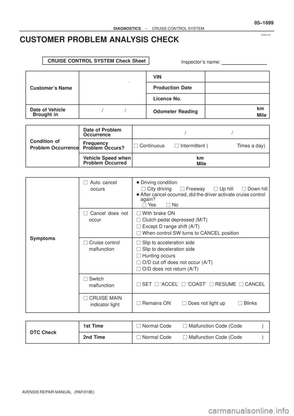
CRUISE CONTROL SYSTEM Check Sheet
Inspector 's name:
Customer 's Name
Date of VehicleVIN
Production Date
Licence No.
Odometer Reading / /km
Mile
Condition of
Problem Occurrence
Date of Problem
Frequency
Occurrence
Problem Occurs?
Vehicle Speed when
Problem Occurred / /
� Continuous � Intermittent ( Times a day)
km
Mile Brought in
� Auto cancel
occurs� Driving condition
� City driving � Freeway � Up hill � Down hill
� After cancel occurred, did the driver activate cruise control
again?
� Yes � No
� Cancel does not
occur� With brake ON
� Clutch pedal depressed (M/T)
� Except D range shift (A/T)
� When control SW turns to CANCEL position
� Cruise control
malfunction� Slip to acceleration side
� Slip to deceleration side
� Hunting occurs
� O/D cut off does not occur (A/T)
� O/D does not return (A/T)
� Switch
malfunction� SET � 'ACCEL' � 'COAST' � RESUME � CANCEL
� Remains ON � Does not light up � Blinks Symptoms
DTC Check1st Time2nd Time
� Normal Code � Malfunction Code (Code )
� Normal Code � Malfunction Code (Code ) � CRUISE MAIN
indicator light
± DIAGNOSTICSCRUISE CONTROL SYSTEM
05±1699
AVENSIS REPAIR MANUAL (RM1018E)
CUSTOMER PROBLEM ANALYSIS CHECK
Page 2003 of 5135
1302Z±03
A77123
SST
A60595E2 VC
± INTAKETURBO CHARGER SYSTEM (1CD±FTV)
13±5
AVENSIS REPAIR MANUAL (RM1018E)
ON±VEHICLE INSPECTION
1. INSPECT INTAKE AIR SYSTEM
(a) Check for leakage or clogging between the air cleaner
housing and turbocharger inlet and between the turbo-
charger outlet and cylinder head.
(1) Clogged air cleaner...Clean or replace element
(2) Hoses collapsed or deformed...Repair or replace
(3) Leakage from connections...Check each connec-
tion and repair
(4) Cracks in components...Check and replace
2. INSPECT EXHAUST SYSTEM
(a) Check for leakage or clogging between the cylinder head
and turbocharger inlet and between the turbocharger out-
let and exhaust pipe.
(1) Deformed components...Repair or replace
(2) Foreign material in passages...Remove
(3) Leakage from components...Repair or replace
(4) Cracks in components...Check and replace
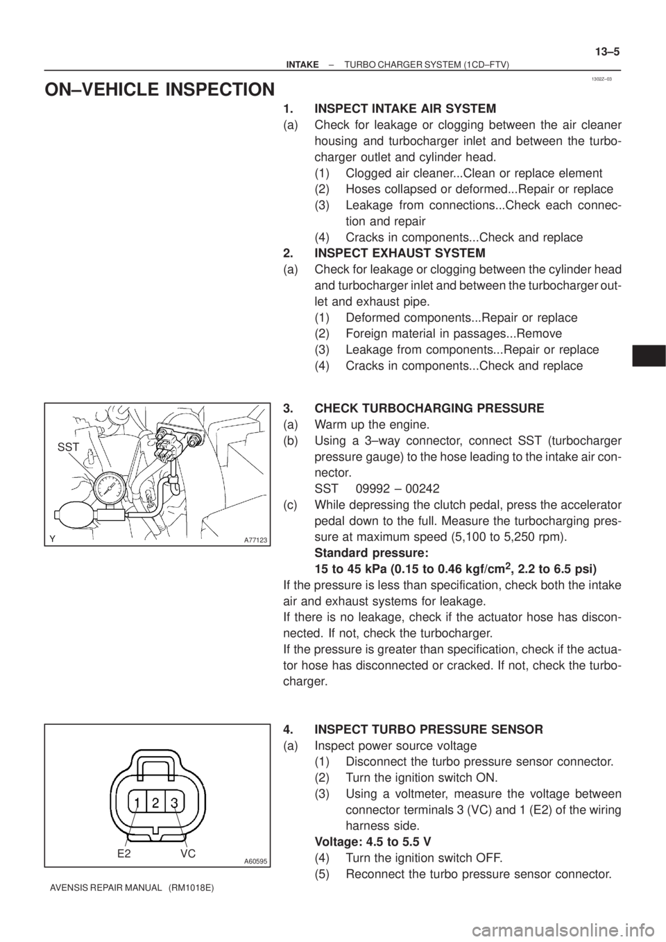
3. CHECK TURBOCHARGING PRESSURE
(a) Warm up the engine.
(b) Using a 3±way connector, connect SST (turbocharger
pressure gauge) to the hose leading to the intake air con-
nector.
SST 09992 ± 00242
(c) While depressing the clutch pedal, press the accelerator
pedal down to the full. Measure the turbocharging pres-
sure at maximum speed (5,100 to 5,250 rpm).
Standard pressure:
15 to 45 kPa (0.15 to 0.46 kgf/cm
2, 2.2 to 6.5 psi)
If the pressure is less than specification, check both the intake
air and exhaust systems for leakage.
If there is no leakage, check if the actuator hose has discon-
nected. If not, check the turbocharger.
If the pressure is greater than specification, check if the actua-
tor hose has disconnected or cracked. If not, check the turbo-
charger.
4. INSPECT TURBO PRESSURE SENSOR
(a) Inspect power source voltage
(1) Disconnect the turbo pressure sensor connector.
(2) Turn the ignition switch ON.
(3) Using a voltmeter, measure the voltage between
connector terminals 3 (VC) and 1 (E2) of the wiring
harness side.
Voltage: 4.5 to 5.5 V
(4) Turn the ignition switch OFF.
(5) Reconnect the turbo pressure sensor connector.
Page 2046 of 5135
A77338
A79320
A79296
A60622
14±30
±
ENGINE MECHANICAL PARTIAL ENGINE ASSY (1ZZ±FE/3ZZ±FE)
AVENSIS REPAIR MANUAL (RM1018E)
32. SEPARATE FLOOR SHIFT CABLE TRANSMISSION CONTROL SELECT (M/T TRANSAXLE) (See page 41±15)
33. SEPARATE FLOOR SHIFT CABLE TRANSMISSION CONTROL SHIFT (M/T TRANSAXLE)
(See page 41±15)
34. SEPARATE FLOOR SHIFT CABLE TRANSMISSION CONTROL SHIFT (A/T TRANSAXLE) (See page 40±11)
35.SEPARATE CLUTCH RELEASE CYLINDER ASSY (M/T TRANSAXLE) (See page 41±15)
36.REMOVE GLOVE COMPARTMENT DOOR ASSY (See page 71±11)
37. REMOVE INSTRUMENT PANEL UNDER COVER SUB±ASSY NO.2
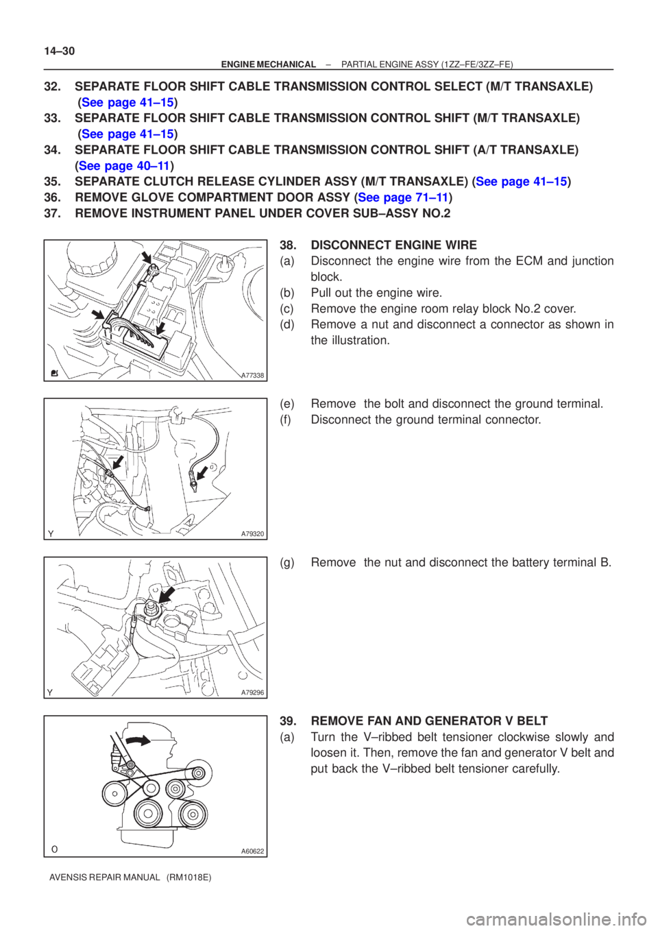
38. DISCONNECT ENGINE WIRE
(a) Disconnect the engine wire from the ECM and junctionblock.
(b) Pull out the engine wire.
(c) Remove the engine room relay block No.2 cover.
(d) Remove a nut and disconnect a connector as shown in the illustration.
(e) Remove the bolt and disconnect the ground terminal.
(f) Disconnect the ground terminal connector.
(g) Remove the nut and disconnect the battery terminal B.
39. REMOVE FAN AND GENERATOR V BELT
(a) Turn the V±ribbed belt tensioner clockwise slowly and loosen it. Then, remove the fan and generator V belt and
put back the V±ribbed belt tensioner carefully.