Page 158 of 5135
Part Tightenedft�lbf kgf�cm N�m
Crankshaft position sensor x Oil pump assy8.89078 in.�lbf
Oil pan sub±assy x Cylinder bloc")
± SERVICE SPECIFICATIONSLUBRICATION
03±29
AVENSIS REPAIR MANUAL (RM1018E)Part Tightenedft�lbf kgf�cm N�m
Crankshaft position sensor x Oil pump assy8.89078 in.�lbf
Oil pan sub±assy x Cylinder block Bolt A
Bolt B
Bolt C
Bolt D42
21
11
12428
214
11 2
12231
15
8
9
Oil pan insulator x Oil pan sub±assy7.57666 in.�lbf
Oil strainer sub±assy x Oil pan sub±assy Bolt
Nut21
13209
13515
10
Oil pan Sub±assy No.2 x Oil pan sub±assy1211 99
Engine oil level sensor x Oil pan sub±assy No.27.07162 in.�lbf
Oil level gage guide x Cylinder block1818413
V±ribbed belt tensioner assy x Oil pump assy3132023
Timing belt idler sub±assy No. 1 x Cylinder head3535726
Timing belt idler sub±assy No. 2 x Oil pump assy4747935
Engine mounting insulator sub±assy RH x Transverse engine engine mount-
ing bracket5253038
Engine mounting insulator sub±assy RH x Body5253038
Engine cover No. 1 x Cylinder head cover sub±assy8.08271 in.�lbf
Engine cover No. 1 x Intake manifold8.08271 in.�lbf
Front wheel RH1031,05076
Oil cooler assy x Cylinder block4545433
Page 159 of 5135

SEAT
TORQUE SPECIFICATION
Part TightenedN�mkgf�cmft�lbf
FRONT SEAT
Seat Inner belt assy x Seat adjuster assy4242831
Sea")
031HN±01
± SERVICE SPECIFICATIONSSEAT
03±71
AVENSIS REPAIR MANUAL (RM1018E)
SEAT
TORQUE SPECIFICATION
Part TightenedN�mkgf�cmft�lbf
FRONT SEAT
Seat Inner belt assy x Seat adjuster assy4242831
Seatback cover bracket x Seat adjuster assy (w/ Side airbag)6.06153 in.�lbf
Seat assy x Body3737527
Seat position airbag sensor x Seat adjuster assy8.08271 in.�lbf
Power seat motor assy (Reclining) x Seat adjuster assy4.54640 in.�lbf
Power seat motor assy (Slide) x Seat adjuster assy Bolt
Nut4.0
3.541
3635 in.�lbf
31 in.�lbf
Power seat motor assy (lifter) x Seat adjuster assy Bolt
Nut2.5
2525
25522 in.�lbf
18
Power seat motor assy (Front vertical) x Seat adjuster assy Bolt
Nut2.5
2525
25522 in.�lbf
18
Front seatback spring assy x Front seat adjuster2525518
REAR SEAT
Armrest assy x Seatback assy8.08271 in.�lbf
Seat belt assy outer center x Seatback frame4242831
Seat belt assy outer center x Body4242831
Seatback lock assy x Seatback frame3030622
Seatback hinge x Seatback frame1818513
Seatback hinge x Body1818513
Seatback hinge center x Body1818513
Seatback hinge center x Seatback frame1818513
Side seatback assy x Body1818513
Bench type seatback assy x Body1818513
Seat cushion frame x Body1818513
Page 165 of 5135
031HC±01
± SERVICE SPECIFICATIONSLIGHTING
03±65
AVENSIS REPAIR MANUAL (RM1018E)
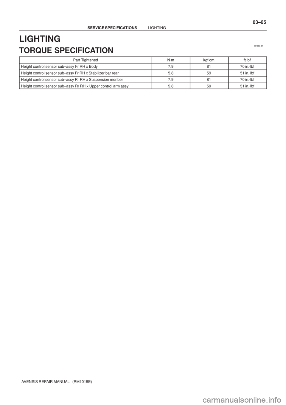
LIGHTING
TORQUE SPECIFICATION
Part TightenedN�mkgf�cmft�lbf
Height control sensor sub±assy Fr RH x Body7.98170 in.�lbf
Height control sensor sub±assy Fr RH x Stabilizer bar rear5.85951 in.�lbf
Height control sensor sub±assy Rr RH x Suspension menber7.98170 in.�lbf
Height control sensor sub±assy Rr RH x Upper control arm assy5.85951 in.�lbf
Page 167 of 5135
031HM±01
± SERVICE SPECIFICATIONSSUPPLEMENTAL RESTRAINT SYSTEM
03±63
AVENSIS REPAIR MANUAL (RM1018E)
SUPPLEMENTAL RESTRAINT SYSTEM
TORQUE SPECIFICATION
Part TightenedN�mkgf�cmft�lbf
Horn button assy x Steering wheel assy8.89078 in.�lbf
Steering wheel assy x Steering column assy5051037
Instrument panel passenger airbag assy x Instrument panel reinforcement2020014
Curtain shield airbag assy x Body3.53631 in.�lbfCurtain shield airbag assy x Body3.5
14
36
143
31 in.lbf
10
Instrument panel airbag assy x Instrument panel reinforcement1818413
Airbag sensor assy center x Body17.517813
Airbag front sensor set bolt7.57666 in.�lbf
Side airbag sensor assy LH x Body17.517813
Airbag sensor rear LH x Body17.517813
Seat position airbag sensor x Front seat8.08271 in.�lbf
Page 179 of 5135

AVENSIS REPAIR MANU")
A75348 � ����
������
AB Temprature SensorB+
Power Transistor
Platinum Hot Wire
Output
Voltage
Platinum Hot Wire
Temprature Sensor 05±24
± DIAGNOSTICSSFI SYSTEM (1ZZ±FE/3ZZ±FE)
AVENSIS REPAIR MANUAL (RM1018E)
DTC P0100 MASS AIR FLOW CIRCUIT MALFUNCTION
CIRCUIT DESCRIPTION
The mass air flow meter uses a platinum hot wire. The hot wire air flow meter consists of a platinum hot wire,
temprature sensor and a control circuit installed in a plastic housing. The hot wire air flow meter works on
the principle that the hot wire and temprature sensor located in the intake air bypass of the housing detect
any changes in the intake air temperature.
The hot wire is maintained at the set temperature by controlling the current flow through the hot wire. This
current flow is then measured as the output voltage of the mass air flow meter.
The circuit is constructed so that the platinum hot wire and temprature sensor provide a bridge circuit, with
the power transistor controlled so that the potential of A and B remains equal to maintain the set temperature.
DTC NoDTC Detecting ConditionTrouble Area
P0100Open or short in mass air flow meter circuit with engine speed
less than 4,000 rpm for more than 3 sec.�Open or short in mass air flow meter circuit
�Mass air flow meter
�ECM
HINT:
After confirming DTC ºP0100º, use the hand±held tester to confirm the air flow ratio in the ºDIAGNOSIS /
OBD/MOBD / DATA LIST / ALLº.
Air Flow Value (gm/sec)Malfunction
Approx. 0.0�Mass air flow meter power source circuit open
�VG circuit open or short
271.0 or more�EVG circuit open
05C68±01
Page 189 of 5135
05B3M±03
A79104
Fuel Pump
Circuit Opening Relay
ECM
DLC3
Camshaft Position
Sensor
Engine Coolant
Temperature Sensor
Camshaft Timig OIL
Control Valve Assy
Crankshaft
Position Sensor
Knock Sensor
Mass Air Flow Meter Assy
Heated Oxygen Sensor
(Bank 1 Sensor 1)
Engine Room R/B No.1
Heated Oxygen Sensor
(Bank 1 Sensor 2)
Engine Room R/B No.4
Ignition Coil and Igniter
Injector
Power Steering Oil
Pressure Switch
Idle Speed Control
Valve Assy
Throttle Position Sensor
Vacuum Switching Valve
(for ISC)
VSV for EVAP
± DIAGNOSTICSSFI SYSTEM (1ZZ±FE/3ZZ±FE)
05±19
AVENSIS REPAIR MANUAL (RM1018E)
LOCATION
Page 190 of 5135

AVENSIS REPAIR MANUAL (RM1018E)
DIAGNOSTIC TROUBLE CODE CHART
HINT:
Parameters listed in the chart may not be exactly the same as your re")
0505J±04
05±16
±
DIAGNOSTICS SFI SYSTEM (1ZZ±FE/3ZZ±FE)
AVENSIS REPAIR MANUAL (RM1018E)
DIAGNOSTIC TROUBLE CODE CHART
HINT:
Parameters listed in the chart may not be exactly the same as your reading due to \
the type of instrument
or other factors.
If a malfunction code is displayed during the DTC check in the check mode, check the circuit f\
or the codes
listed in the table below. For details of each code, refer to the ''See page '' under the respective ''DTC No.''
in the DTC chart.
DTC No.
(See page)Detection ItemTrouble Area*1
CHK ENGMemory
P0100
(05±24)Mass Air Flow Circuit Malfunc-
tion� Open or short in mass air flow meter circuit
� Mass air flow meter
� ECM
��
P0110
(05±30)Intake Air Temperature Circuit
Malfunction� Open or short in intake air temp. sensor circuit
� Intake air temp. sensor (built into mass air flow meter)
� ECM
��
P0115
(05±34)Engine Coolant Temperature Cir-
cuit Malfunction� Open or short in engine coolant temperature sensor circuit
� Engine coolant temperature sensor
� ECM
��
P0116
(05±38)Engine Coolant Temperature Cir-
cuit Range/Performance Prob-
lem� Engine coolant temperature sensor
� Thermostat��
P0120
(05±39)Throttle Pedal Position Sensor/
Switch ºAº Circuit Malfunction� Open or short in throttle position sensor circuit
� Throttle position sensor
� ECM
��
P0121
(05±44)Throttle Pedal Position Sensor/
Switch ºAº Circuit Range/Perfor-
mance Problem
� Throttle position sensor��
P0125
(05±45)Insufficient Coolant Temp. for
Closed Loop Fuel Control
� Open or short in heated oxygen sensor circuit
� Heated oxygen sensor
� Air induction system
� Fuel pressure
� Injector
� Gas leakage on exhaust system
� ECM
��
P0130*3
(05±54)
Oxygen Sensor Circuit Malfunc-
tion (Bank 1 Sensor 1)
�Open or short in heated oxygen sensor circuit
� Heated oxygen sensor
� Air induction system
� Fuel pressure
� Injector
��
P0133*3
(05±60)
Oxygen Sensor Circuit Slow Re-
sponse (Bank 1 Sensor 1)
�Open or short in heated oxygen sensor circuit
� Heated oxygen sensor
� Air induction system
� Fuel pressure
� Injector
� ECM
��
P0135
(05±65)Oxygen Sensor Heater Circuit
Malfunction (Bank 1 Sensor 1)� Open or short in heater circuit of heated oxygen sensor
� Heated oxygen sensor heater
� ECM
��
P0136
(05±54)Oxygen Sensor Circuit Malfunc-
tion (Bank 1 Sensor 2)� Open or short in heated oxygen sensor circuit
� Heated oxygen sensor��
P0141
(05±65)Oxygen Sensor Heater Circuit
Malfunction (Bank 1 Sensor 2)� Open or short in heater circuit of heated oxygen sensor
� Heated oxygen sensor heater
� ECM
��
Page 191 of 5135

05±17
AVENSIS REPAIR MANUAL (RM1018E)P0171*
3
(05±67)
System too Lean (Fuel Trim)
(Bank1)
�
Air induction system
� Injector blockage
� PCV hose
� Mass a")
±
DIAGNOSTICS SFI SYSTEM (1ZZ±FE/3ZZ±FE)
05±17
AVENSIS REPAIR MANUAL (RM1018E)P0171*
3
(05±67)
System too Lean (Fuel Trim)
(Bank1)
�
Air induction system
� Injector blockage
� PCV hose
� Mass air flow meter
� Engine coolant temperature sensor
� Fuel pressure
� Open or short in heated oxygen sensor circuit
� Heated oxygen sensor
� ECM
��
P0172*3
(05±67)
System too Rich (Fuel Trim)
(Bank1)
�Injector leak, blockage
� Mass air flow meter
� Engine coolant temperature sensor
� Ignition system
� Fuel pressure
� Open or short in heated oxygen sensor circuit
� Gas leakage in exhaust system
� Heated oxygen sensor
� ECM
��
P0300*3
(05±73)
Random/Multiple Cylinder Misfire
Detected�Open or short in engine wire
� Connector connection
Vac m hose connectionP0301*3
(05±73)Cylinder 1 Misfire Detected
�Vacuum hose connection
� PCV hose
� Ignition system
P0302*3
(05±73)Cylinder 2 Misfire Detected
�Injector
� Fuel pressure
� Mass air flow meter
��
P0303*3
(05±73)Cylinder 3 Misfire Detected
�Mass air flow meter
�Engine coolant temperature sensor
� Compression pressure
�Valve clearance
P0304*3
(05±73)Cylinder 4 Misfire Detected
�Valve clearance
� Valve timing
� ECM
P0325
(05±81)Knock Sensor 1 Circuit Malfunc-
tion (Bank 1)� Open or short in knock sensor circuit
� Knock sensor (under±torqued or loose)
� ECM
��
P0335
(05±84)Crankshaft Position Sensor ºAº
Circuit Malfunction
� Open or short in crankshaft position sensor circuit
� Crankshaft position sensor
� Crank angle sensor plate
� ECM
��
P0340
(05±88)Camshaft Position Sensor Circuit
Malfunction
� Open or short in camshaft position sensor circuit
� Camshaft position sensor
� Intake camshaft
� Timing chain has jumped a tooth
� ECM
��
P0420*3
(05±91)
Catalyst System Efficiency Be-
low Threshold (Bank 1)
�Gas leakage in exhaust system
� Heated oxygen sensor
� Three±way catalytic converter
� ECM
��
P0443
(05±94)Evaporative Emission Control
System Purge Control Vent Cir-
cuit Malfunction� Open or short in VSV for EVAP circuit
� VSV for EVAP
� ECM
��
P0500
(05±98)Vehicle Speed Sensor Malfunc-
tion
� Open or short in speed sensor circuit
� Speed sensor
� Combination meter
� ECM
� Skid control ECU
��