Page 2557 of 5135
C80976
28±2
±
TIRE & WHEEL WHEEL AND TIRE SYSTEM
AVENSIS REPAIR MANUAL (RM1018E)
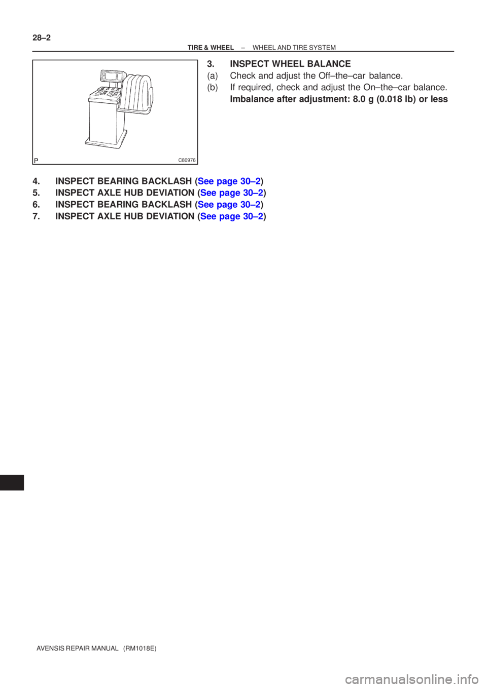
3. INSPECT WHEEL BALANCE
(a) Check and adjust the Off±the±car balance.
(b) If required, check and adjust the On±the±car balance. Imbalance after adjustment: 8.0 g (0.018 lb) or less
4.INSPECT BEARING BACKLASH (See page 30±2)
5.INSPECT AXLE HUB DEVIATION (See page 30±2)
6.INSPECT BEARING BACKLASH (See page 30±2)
7.INSPECT AXLE HUB DEVIATION (See page 30±2)
Page 2602 of 5135
G21543
F44820
������F45267
30±34
±
DRIVE SHAFT / PROPELLER SHAFT REAR AXLE CARRIER SUB±ASSY LH
AVENSIS REPAIR MANUAL (RM1018E)
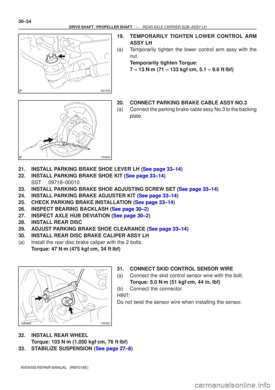
19.TEMPORARILY TIGHTEN LOWER CONTROL ARM ASSY LH
(a)Temporarily tighten the lower control arm assy with the
nut.
Temporarily tighten Torque:
7 ± 13 N �m (71 ± 133 kgf �cm, 5.1 ± 9.6 ft �lbf)
20.CONNECT PARKING BRAKE CABLE ASSY NO.3
(a)Connect the parking brake cable assy No.3 to the backing plate.
21.INSTALL PARKING BRAKE SHOE LEVER LH (See page 33±14)
22.INSTALL PARKING BRAKE SHOE KIT (See page 33±14) SST 09718±00010
23.INSTALL PARKING BRAKE SHOE ADJUSTING SCREW SET (See page 33±14)
24.INSTALL PARKING BRAKE ADJUSTER KIT (See page 33±14)
25.CHECK PARKING BRAKE INSTALLATION (See page 33±14)
26.INSPECT BEARING BACKLASH (See page 30±2)
27.INSPECT AXLE HUB DEVIATION (See page 30±2)
28. INSTALL REAR DISC
29.ADJUST PARKING BRAKE SHOE CLEARANCE (See page 33±14)
30. INSTALL REAR DISC BRAKE CALIPER ASSY LH
(a) Install the rear disc brake caliper with the 2 bolts. Torque: 47 N �m (475 kgf �cm, 34 ft �lbf)
31. CONNECT SKID CONTROL SENSOR WIRE
(a) Connect the skid control sensor wire with the bolt. Torque: 5.0 N �m (51 kgf �cm, 44 in. �lbf)
(b) Connect the connector.
HINT:
Do not twist the sensor wire when installing the sensor.
32. INSTALL REAR WHEEL Torque: 103 N �m (1,050 kgf �cm, 76 ft �lbf)
33.STABILIZE SUSPENSION (See page 27±8)
Page 2605 of 5135
320VV±01
G23167
F08657
BoltSST
SST
Bolt
±
BRAKE SKID CONTROL SENSOR
32±61
AVENSIS REPAIR MANUAL (RM1018E)
SKID CONTROL SENSOR
REPLACEMENT
HINT:
Replace the RH side by using the same procedures as those for the LH side.
1. REMOVE REAR WHEEL
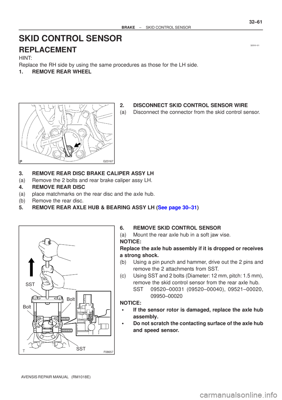
2. DISCONNECT SKID CONTROL SENSOR WIRE
(a) Disconnect the connector from the skid control sensor.
3. REMOVE REAR DISC BRAKE CALIPER ASSY LH
(a) Remove the 2 bolts and rear brake caliper assy LH.
4. REMOVE REAR DISC
(a) place matchmarks on the rear disc and the axle hub.
(b) Remove the rear disc.
5.REMOVE REAR AXLE HUB & BEARING ASSY LH (See page 30±31) 6. REMOVE SKID CONTROL SENSOR
(a) Mount the rear axle hub in a soft jaw vise.
NOTICE:
Replace the axle hub assembly if it is dropped or receives
a strong shock.
(b) Using a pin punch and hammer, drive out the 2 pins andremove the 2 attachments from SST.
(c) Using SST and 2 bolts (Diameter: 12 mm, pitch: 1.5 mm), remove the skid control sensor from the rear axle hub.
SST 09520±00031 (09520±00040), 09521±00020, 09950±00020
NOTICE:
�If the sensor rotor is damaged, replace the axle hub
assembly.
�Do not scratch the contacting surface of the axle hub
and speed sensor.
Page 2606 of 5135
G23168
F08658
SST
G23167
32±62
±
BRAKE SKID CONTROL SENSOR
AVENSIS REPAIR MANUAL (RM1018E)
7. INSTALL SKID CONTROL SENSOR
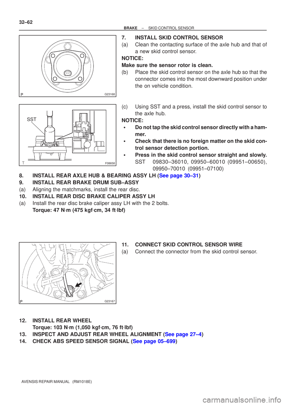
(a) Clean the contacting surface of the axle hub and that of a new skid control sensor.
NOTICE:
Make sure the sensor rotor is clean.
(b) Place the skid control sensor on the axle hub so that the connector comes into the most downward position under
the on vehicle condition.
(c) Using SST and a press, install the skid control sensor to the axle hub.
NOTICE:
�Do not tap the skid control sensor directly with a ham-
mer.
�Check that there is no foreign matter on the skid con-
trol sensor detection portion.
�Press in the skid control sensor straight and slowly.
SST 09830±36010, 09950±60010 (09951±00650), 09950±70010 (09951±07100)
8.INSTALL REAR AXLE HUB & BEARING ASSY LH (See page 30±31)
9. INSTALL REAR BRAKE DRUM SUB±ASSY
(a) Aligning the matchmarks, install the rear disc.
10. INSTALL REAR DISC BRAKE CALIPER ASSY LH
(a) Install the rear disc brake caliper assy LH with the 2 bolts. Torque: 47 N �m (475 kgf �cm, 34 ft �lbf)
11. CONNECT SKID CONTROL SENSOR WIRE
(a) Connect the connector from the skid control sensor.
12. INSTALL REAR WHEEL Torque: 103 N �m (1,050 kgf �cm, 76 ft �lbf)
13.INSPECT AND ADJUST REAR WHEEL ALIGNMENT (See page 27±4)
14.CHECK ABS SPEED SENSOR SIGNAL (See page 05±699)
Page 2751 of 5135
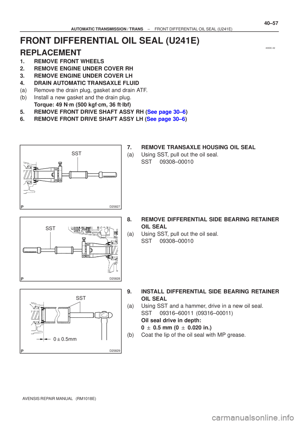
400DE±02
D25827
SST
D25828
SST
D25829
SST
0 � 0.5mm
±
AUTOMATIC TRANSMISSION / TRANS FRONT DIFFERENTIAL OIL SEAL (U241E)
40±57
AVENSIS REPAIR MANUAL (RM1018E)
FRONT DIFFERENTIAL OIL SEAL (U241E)
REPLACEMENT
1. REMOVE FRONT WHEELS
2. REMOVE ENGINE UNDER COVER RH
3. REMOVE ENGINE UNDER COVER LH
4. DRAIN AUTOMATIC TRANSAXLE FLUID
(a) Remove the drain plug, gasket and drain ATF.
(b) Install a new gasket and the drain plug.
Torque: 49 N �m (500 kgf �cm, 36 ft �lbf)
5.REMOVE FRONT DRIVE SHAFT ASSY RH (See page 30±6)
6.REMOVE FRONT DRIVE SHAFT ASSY LH (See page 30±6)
7. REMOVE TRANSAXLE HOUSING OIL SEAL
(a) Using SST, pull out the oil seal.SST 09308±00010
8. REMOVE DIFFERENTIAL SIDE BEARING RETAINER OIL SEAL
(a) Using SST, pull out the oil seal. SST 09308±00010
9. INSTALL DIFFERENTIAL SIDE BEARING RETAINER OIL SEAL
(a) Using SST and a hammer, drive in a new oil seal.
SST 09316±60011 (09316±00011)
Oil seal drive in depth:
0 � 0.5 mm (0 � 0.020 in.)
(b) Coat the lip of the oil seal with MP grease.
Page 2769 of 5135
4200B±04
±
CLUTCH CLUTCH SYSTEM (MTM)
42±1
AVENSIS REPAIR MANUAL (RM1018E)
CLUTCH SYSTEM (MTM)
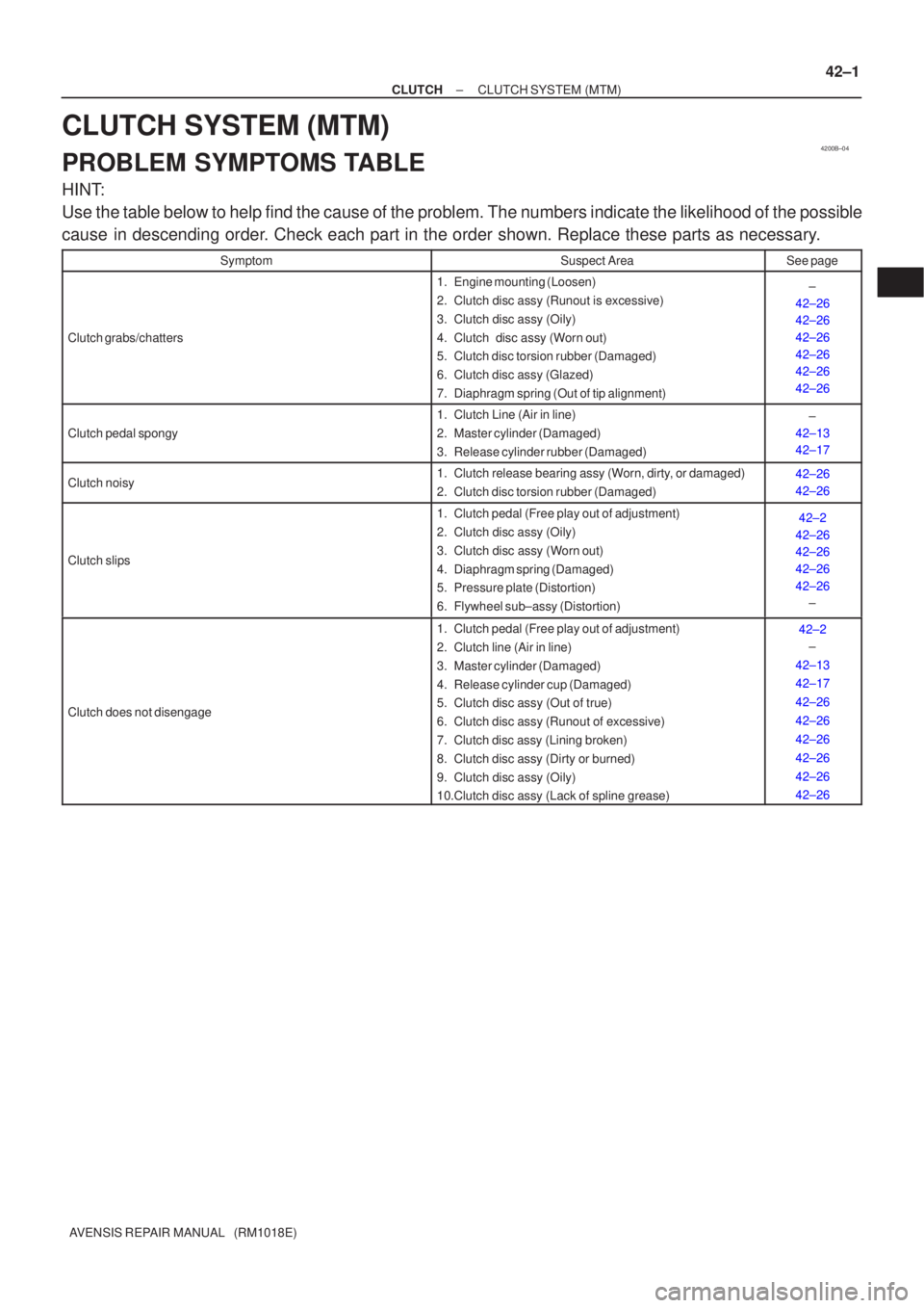
PROBLEM SYMPTOMS TABLE
HINT:
Use the table below to help find the cause of the problem. The numbers indi\
cate the likelihood of the possible
cause in descending order. Check each part in the order shown. Replace these parts as necessary.
SymptomSuspect AreaSee page
Clutch grabs/chatters
1. Engine mounting (Loosen)
2. Clutch disc assy (Runout is excessive)
3. Clutch disc assy (Oily)
4. Clutch disc assy (Worn out)
5. Clutch disc torsion rubber (Damaged)
6. Clutch disc assy (Glazed)
7. Diaphragm spring (Out of tip alignment)±
42±26
42±26
42±26
42±26
42±26
42±26
Clutch pedal spongy
1. Clutch Line (Air in line)
2. Master cylinder (Damaged)
3. Release cylinder rubber (Damaged)±
42±13
42±17
Clutch noisy1. Clutch release bearing assy (Worn, dirty, or damaged)
2. Clutch disc torsion rubber (Damaged)42±26
42±26
Clutch slips
1. Clutch pedal (Free play out of adjustment)
2. Clutch disc assy (Oily)
3. Clutch disc assy (Worn out)
4. Diaphragm spring (Damaged)
5. Pressure plate (Distortion)
6. Flywheel sub±assy (Distortion)42±2
42±26
42±26
42±26
42±26 ±
Clutch does not disengage
1. Clutch pedal (Free play out of adjustment)
2. Clutch line (Air in line)
3. Master cylinder (Damaged)
4. Release cylinder cup (Damaged)
5. Clutch disc assy (Out of true)
6. Clutch disc assy (Runout of excessive)
7. Clutch disc assy (Lining broken)
8. Clutch disc assy (Dirty or burned)
9. Clutch disc assy (Oily)
10.Clutch disc assy (Lack of spline grease)42±2
±
42±13
42±17
42±26
42±26
42±26
42±26
42±26
42±26
Page 2798 of 5135

PROBLEM SYMPTOMS TABLE
HINT:
Use the table below to help you find the cause of the problem. The numbers \
indi")
5100G±06
51±2
±
POWER STEERING POWER STEERING SYSTEM
AVENSIS REPAIR MANUAL (RM1018E)
PROBLEM SYMPTOMS TABLE
HINT:
Use the table below to help you find the cause of the problem. The numbers \
indicate the likelihood of the
cause in the descending order. Check each part in the order shown. Replace parts if necessary.
Hydraulic Power Steering System:
SymptomSuspect AreaSee page
Hard steering
3. Tires (Improperly inflated)
4. Power steering fluid level (Low)
5. Drive belt (Loose)
6. Front wheel alignment (Incorrect)
7. Steering system joints (Worn)
8. Suspension arm ball joints (Worn)
9. Steering column (Binding)
10.Power steering vane pump AZ Series: 1CD±FTV:
11. Power steering gear28±1
51±4
26±6 ±
26±24 ±
51±9
51±19 51±4
51±36
Poor return
1. Tires (Improperly inflated)
2. Front wheel alignment (Incorrect)
3. Steering column (Binding)
4. Power steering gear28±1
26±6 ±
51±4
51±36
Excessive play
1. Steering system joints (Worn)
2. Suspension arm ball joints (Worn)
3. Intermediate shaft, Sliding yoke (Worn)
4. Front wheel bearing (Worn)
5. Power steering gear±
26±24 ±
30±2
51±4
51±36
Abnormal noise
1. Power steering fluid level (Low)
2. Steering system joints (Worn)
3. Power steering vane pump AZ Series: 1CD±FTV:
4. Power steering gear51±4
±
51±9
51±19 51±4
51±36
Page 2799 of 5135
±
POWER STEERING POWER STEERING SYSTEM
51±3
AVENSIS REPAIR MANUAL (RM1018E)
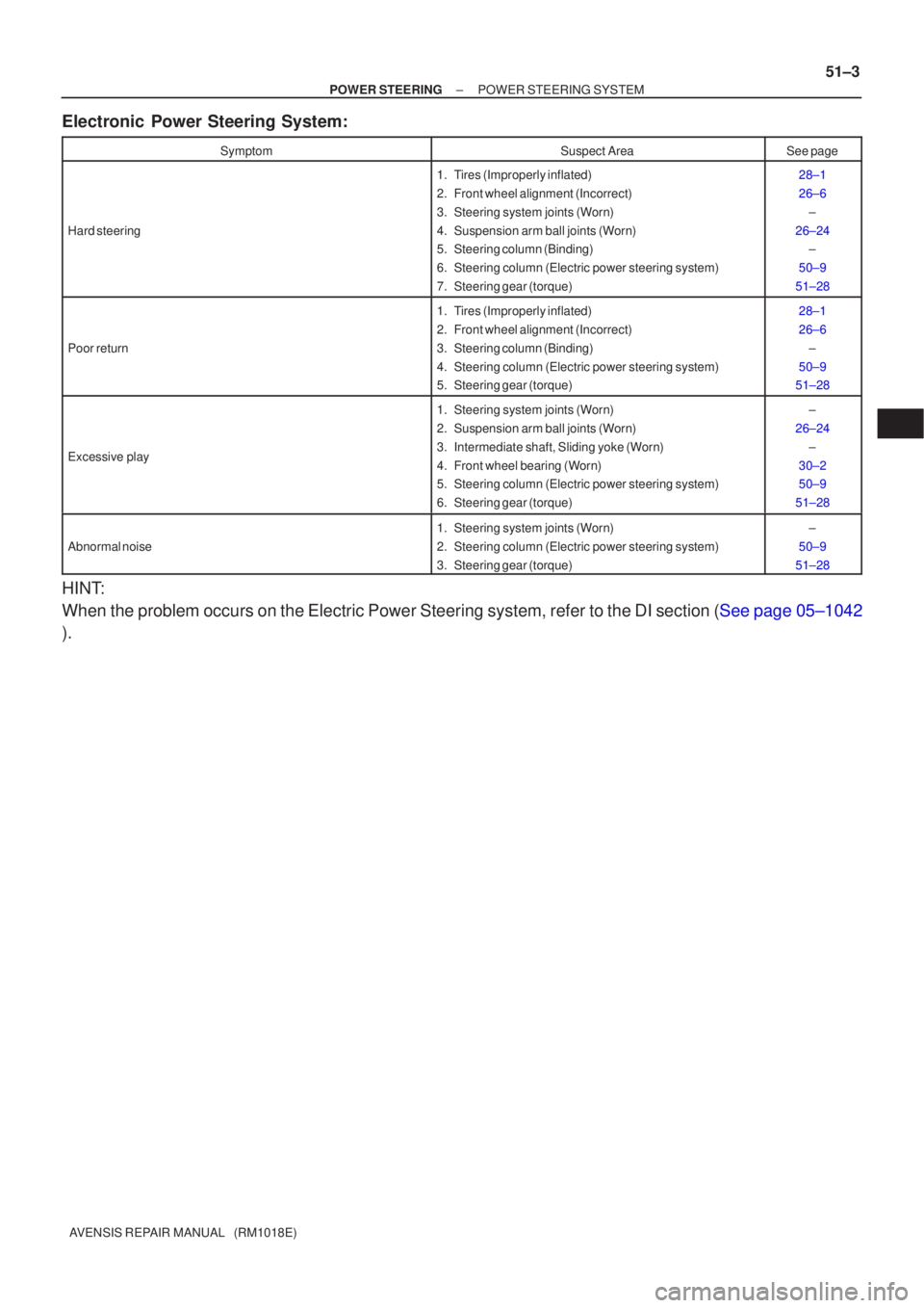
Electronic Power Steering System:
SymptomSuspect AreaSee page
Hard steering
1. Tires (Improperly inflated)
2. Front wheel alignment (Incorrect)
3. Steering system joints (Worn)
4. Suspension arm ball joints (Worn)
5. Steering column (Binding)
6. Steering column (Electric power steering system)
7. Steering gear (torque)28±1
26±6
±
26±24 ±
50±9
51±28
Poor return
1. Tires (Improperly inflated)
2. Front wheel alignment (Incorrect)
3. Steering column (Binding)
4. Steering column (Electric power steering system)
5. Steering gear (torque)28±1
26±6 ±
50±9
51±28
Excessive play
1. Steering system joints (Worn)
2. Suspension arm ball joints (Worn)
3. Intermediate shaft, Sliding yoke (Worn)
4. Front wheel bearing (Worn)
5. Steering column (Electric power steering system)
6. Steering gear (torque)±
26±24 ±
30±2
50±9
51±28
Abnormal noise
1. Steering system joints (Worn)
2. Steering column (Electric power steering system)
3. Steering gear (torque)±
50±9
51±28
HINT:
When the problem occurs on the Electric Power Steering system, refer to \
the DI section (See page 05±1042
).