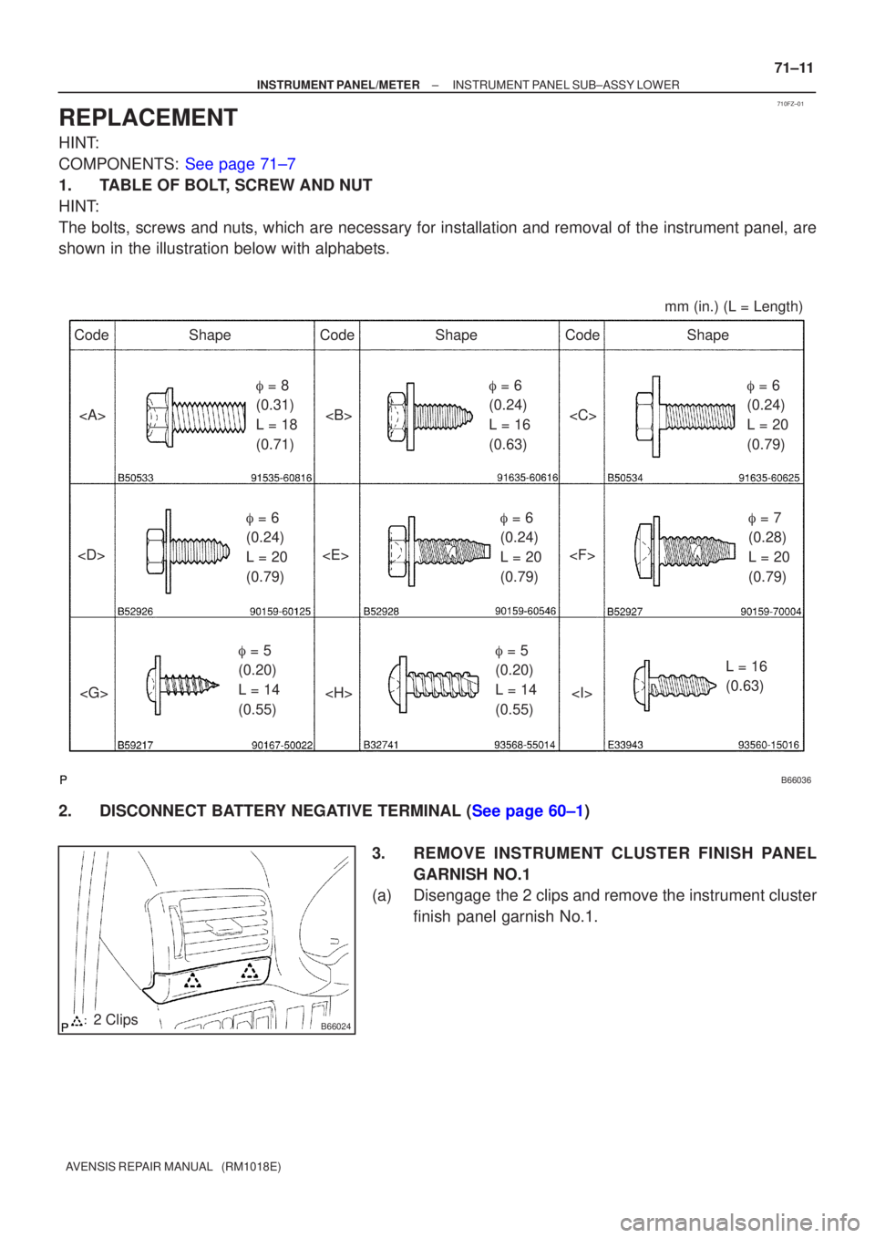
Page 3221 of 5135
Page 3222 of 5135
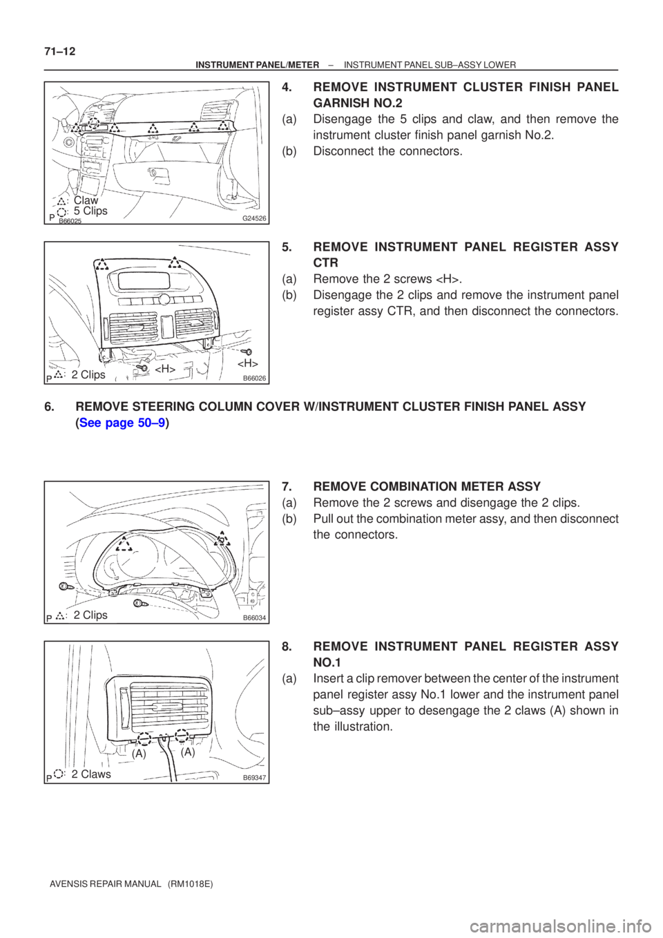
������G245265 Clips Claw
B660262 Clips
B660342 Clips
B693472 Claws
(A)(A)
71±12
±
INSTRUMENT PANEL/METER INSTRUMENT PANEL SUB±ASSY LOWER
AVENSIS REPAIR MANUAL (RM1018E)
4.REMOVE INSTRUMENT CLUSTER FINISH PANEL GARNISH NO.2
(a)Disengage the 5 clips and claw, and then remove the
instrument cluster finish panel garnish No.2.
(b)Disconnect the connectors.
5.REMOVE INSTRUMENT PANEL REGISTER ASSY CTR
(a)Remove the 2 screws .
(b)Disengage the 2 clips and remove the instrument panel register assy CTR, and then disconnect the connectors.
6.REMOVE STEERING COLUMN COVER W/INSTRUMENT CLUSTER FINISH PANEL ASSY (See page 50±9)
7. REMOVE COMBINATION METER ASSY
(a) Remove the 2 screws and disengage the 2 clips.
(b) Pull out the combination meter assy, and then disconnectthe connectors.
8. REMOVE INSTRUMENT PANEL REGISTER ASSY NO.1
(a) Insert a clip remover between the center of the instrument
panel register assy No.1 lower and the instrument panel
sub±assy upper to desengage the 2 claws (A) shown in
the illustration.
Page 3225 of 5135
B70029: 4 Clips
A/T Transaxle:
M/T Transaxle:
B66045Claw
±
INSTRUMENT PANEL/METER INSTRUMENT PANEL SUB±ASSY LOWER
71±15
AVENSIS REPAIR MANUAL (RM1018E)
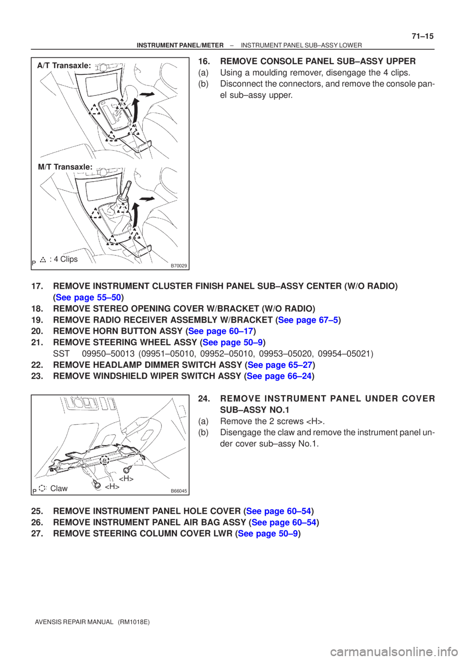
16.REMOVE CONSOLE PANEL SUB±ASSY UPPER
(a)Using a moulding remover, disengage the 4 clips.
(b)Disconnect the connectors, and remove the console pan-
el sub±assy upper.
17.REMOVE INSTRUMENT CLUSTER FINISH PANEL SUB±ASSY CENTER (W/O RADIO) (See page 55±50)
18.REMOVE STEREO OPENING COVER W/BRACKET (W/O RADIO)
19.REMOVE RADIO RECEIVER ASSEMBLY W/BRACKET (See page 67±5)
20.REMOVE HORN BUTTON ASSY (See page 60±17)
21.REMOVE STEERING WHEEL ASSY (See page 50±9) SST09950±50013 (09951±05010, 09952±05010, 09953±05020, 09954±\
05021)
22.REMOVE HEADLAMP DIMMER SWITCH ASSY (See page 65±27)
23.REMOVE WINDSHIELD WIPER SWITCH ASSY (See page 66±24)
24.REMOVE INSTRUMENT PANEL UNDER COVERSUB±ASSY NO.1
(a)Remove the 2 screws .
(b)Disengage the claw and remove the instrument panel un- der cover sub±assy No.1.
25.REMOVE INSTRUMENT PANEL HOLE COVER (See page 60±54)
26.REMOVE INSTRUMENT PANEL AIR BAG ASSY (See page 60±54)
27.REMOVE STEERING COLUMN COVER LWR (See page 50±9)
Page 3232 of 5135
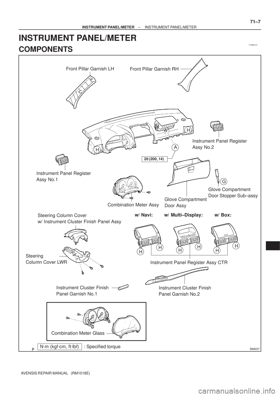
710G2±01
B66037
Front Pillar Garnish LH
Front Pillar Garnish RH
Instrument Panel Register
Assy No.2
Instrument Panel Register
Assy No.1
Steering Column Cover
w/ Instrument Cluster Finish Panel AssyCombination Meter AssyGlove Compartment
Door AssyGlove Compartment
Door Stopper Sub±assy
w/ Multi±Display: w/ Box: w/ Navi:
Instrument Panel Register Assy CTR
Instrument Cluster Finish
Panel Garnish No.2 Steering
Column Cover LWR
Instrument Cluster Finish
Panel Garnish No.1
Combination Meter Glass
N´m (kgf´cm, ft´lbf) : Specified torque
A
G
H
H
HHHHHH
20 (200, 14)
± INSTRUMENT PANEL/METERINSTRUMENT PANEL/METER
71±7
AVENSIS REPAIR MANUAL (RM1018E)
INSTRUMENT PANEL/METER
COMPONENTS
Page 4004 of 5135
670SG±02
67±24
±
AUDIO & VISUAL SYSTEM ANTENNA CORD SUB±ASSY NO.3
AVENSIS REPAIR MANUAL (RM1018E)
ANTENNA CORD SUB±ASSY NO.3
REPLACEMENT
1 . DISCONNEC T B ATTE RY NEG ATIVE TERMINAL ( See page 60±1)
2 . REMOVE INSTRUMENT CLUSTER FINISH P ANEL GARNISH NO.2 ( See page 71±11 )
3. REMOVE INSTRUMENT PANEL REGISTER ASSY CTR (W/ NAVIGATION SYSTEM) (See page 67±6 )
4 . REMOVE SHIFT LEVER KNOB SUB±ASSY (M/T TRANSAXLE) ( See page 41±11 )
5 . REMOVE CONSOLE PANEL SUB±ASSY UPPER ( See page 71±11 )
6 . REMOVE RADIO RECEIVER ASSEMB LY W/BRACKET ( See page 67±5)
7 . REMOVE CONSOLE BOX ASSY RR ( See page 71±11 )
8 . REMOVE HE ATER T O REGISTER DUCT NO.2 ( See page 71±11 )
9 . REMOVE FRONT DOOR SCUFF PL ATE RH ( See page 76±36 )
10 . REMOVE REAR DOOR SCUFF PL ATE RH ( See page 76±36 )
1 1 . REMOVE COWL SIDE TRIM BOARD RH ( See page 76±36)
12 . REMOVE FRONT DOOR OPENING TRIM WE ATHERSTRIP RH ( See page 76±36 )
13 . REMOVE REAR DOOR OPENING TRIM WE ATHERSTRIP RH ( See page 76±36 )
14. REMOVE REAR SEAT CUSHION ASSEMBLY (See page 40/60 FOLDING FLIP±UP CUSHION 72±21 , 40/60 FOLDING 72±27 )
15. REMOVE REAR SEATBACK ASSY (See page 40/60 FOLDING FLIP±UP CUSHION 72±21 , 40/60 FOLDING 72±27 )
16. REMOVE REAR SIDE SEAT BACK ASSY RH (See page 40/60 FOLDING FLIP±UP CUSHION 72±21 , 40/60 FOLDING 72±27 )
17 . REMOVE P ACKAGE TR AY TRIM P ANEL ASSY ( See page 76±45 )
18 . REMOVE REAR FLOOR FINISH PL ATE ( See page 76±45 )
19 . REMOVE DECK TRIM SIDE P ANEL ASSY RH ( See page 76±45)
20 . REMOVE ROOF SIDE GARNISH INNER RH ( See page 76±45)
21 . REMOVE FRONT SE AT ASSY RH ( See page POWER SE AT 72± 11 , MANUAL SE AT 72±16 )
22. REMOVE FLOOR CARPET ASSY FRONT
Page 4007 of 5135
670SC±03
67±16
±
AUDIO & VISUAL SYSTEM AMPLIFIER ANTENNA ASSY (SEDAN MODELS)
AVENSIS REPAIR MANUAL (RM1018E)
AMPLIFIER ANTENNA ASSY (SEDAN MODELS)
REPLACEMENT
1 . DISCONNEC T B ATTE RY NEG ATIVE TERMINAL ( See page 60±1)
2 . REMOVE INSTRUMENT CLUSTER FINISH P ANEL GARNISH NO.2 ( See page 71±11 )
3. REMOVE INSTRUMENT PANEL REGISTER ASSY CTR (W/ NAVIGATION SYSTEM) (See page 67±6 )
4 . REMOVE SHIFT LEVER KNOB SUB±ASSY (M/T TRANSAXLE) ( See page 41±11 )
5 . REMOVE CONSOLE PANEL SUB±ASSY UPPER ( See page 71±11 )
6 . REMOVE RADIO RECEIVER ASSEMB LY W/BRACKET ( See page 67±5)
7 . REMOVE CONSOLE BOX ASSY RR ( See page 71±11 )
8 . REMOVE HE ATER T O REGISTER DUCT NO.2 ( See page 71±11 )
9 . REMOVE FRONT SE AT ASSY RH ( See page POWER SE AT 72± 11 , MANUAL SE AT 72±16 )
10 . REMOV E FRONT DOOR SCUFF PL ATE RH ( See page 76±36 )
1 1 . REMOVE REAR DOOR SCUFF PL ATE RH ( See page 76±36 )
12 . REMOVE COWL SIDE TRIM BOARD RH ( See page 76±36)
13 . REMOVE FRONT DOOR OPENING TRIM WE ATHERSTRIP RH ( See page 76±36 )
14 . REMOVE REAR DOOR OPENING TRIM WE ATHERSTRIP RH ( See page 76±36 )
15 . REMOVE REAR SE AT CUSHION ASSEMB LY ( See page 72±32 )
16 . REMOVE REAR SE ATBACK ASSY ( See page 40/60 FOLDING 72±27 , UNITED FIXED 72±32 )
17 . REMOVE ROOF SIDE GARNISH INNER RH ( See page 76±36)
18. REMOVE FLOOR CARPET ASSY FRONT
Page 5090 of 5135
Page 5091 of 5135
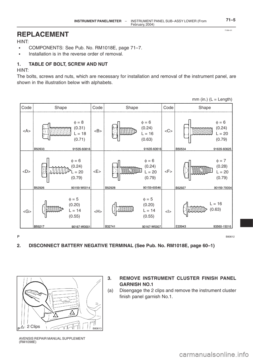
B80614
5 Clips
Claw
B806152 Clips
B660342 Clips
B693472 Claws
(A)(A) 71–6
– INSTRUMENT PANEL/METERINSTRUMENT PANEL SUB–ASSY LOWER (From
February, 2004)
AVENSIS REPAIR MANUAL SUPPLEMENT
(RM1098E)
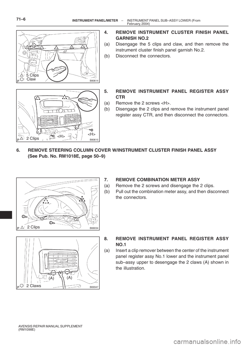
4. REMOVE INSTRUMENT CLUSTER FINISH PANEL
GARNISH NO.2
(a) Disengage the 5 clips and claw, and then remove the
instrument cluster finish panel garnish No.2.
(b) Disconnect the connectors.
5. REMOVE INSTRUMENT PANEL REGISTER ASSY
CTR
(a) Remove the 2 screws .
(b) Disengage the 2 clips and remove the instrument panel
register assy CTR, and then disconnect the connectors.
6. REMOVE STEERING COLUMN COVER W/INSTRUMENT CLUSTER FINISH PANEL ASSY
(See Pub. No. RM1018E, page 50–9)
7. REMOVE COMBINATION METER ASSY
(a) Remove the 2 screws and disengage the 2 clips.
(b) Pull out the combination meter assy, and then disconnect
the connectors.
8. REMOVE INSTRUMENT PANEL REGISTER ASSY
NO.1
(a) Insert a clip remover between the center of the instrument
panel register assy No.1 lower and the instrument panel
sub–assy upper to desengage the 2 claws (A) shown in
the illustration.