Page 5040 of 5135
![TOYOTA AVENSIS 2005 Service Repair Manual –
DIAGNOSTICS ELECTRONIC CONTROLLED AUTOMATIC
TRANSAXLE [ECT] (U341E) (From February, 2004)05–269
AVENSIS REPAIR MANUAL SUPPLEMENT
(RM1098E)
INSPECTION PROCEDURE
HINT:
Performing the Intelligent](/manual-img/14/57441/w960_57441-5039.png "TOYOTA AVENSIS 2005 Service Repair Manual –
DIAGNOSTICS ELECTRONIC CONTROLLED AUTOMATIC
TRANSAXLE [ECT] (U341E) (From February, 2004)05–269
AVENSIS REPAIR MANUAL SUPPLEMENT
(RM1098E)
INSPECTION PROCEDURE
HINT:
Performing the Intelligent")
–
DIAGNOSTICS ELECTRONIC CONTROLLED AUTOMATIC
TRANSAXLE [ECT] (U341E) (From February, 2004)05–269
AVENSIS REPAIR MANUAL SUPPLEMENT
(RM1098E)
INSPECTION PROCEDURE
HINT:
Performing the Intelligent Tester II Active Test allows relay, Vacuum Switching Valve (VSV), actuator and
other items to be operated without removing any parts. Performing the Active Test early in troubleshooting
is one way to shorten labor time. The Data List can be displayed during \
the Active Test.
(a) Warm up the engine.
(b) Turn the ignition switch off.
(c) Connect the Intelligent Tester II to the DLC3.
(d) Turn the ignition switch to the ON position.
(e) Turn on the tester.
(f) Clear the DTC.
(g) Select the item ”Enter / Power train / Engine and ECT / Active Test / Control the Shift Position”.
(h) Follow the instructions on the tester and read the Active Test.
HINT:
While driving, the shift position can be forcibly changed with the Intel\
ligent Tester II.
Comparing the shift position commanded by the ACTIVE TEST with the actua\
l shift position enables you
to confirm the problem ( see page 05–241).
ItemTest DetailsDiagnostic Note
Control the Shift Position
[Test Details]
Operate the shift solenoid valve and set the each shift position by your\
-
self.
[Vehicle Condition]
�IDL: ON
� Less than 50 km/h (31 mph)
[Others]
� Press ” →” button: Shift up
� Press ” ←” button: Shift down
Possible to check the operation of
the shift solenoid valves.
HINT:
�This test can be conducted when the vehicle speed is 50 km/h (31 mph) or l\
ess.
�The shift position commanded by the ECM is shown in the DATA LIST (Shift Status) display on the
Intelligent Tester II.
1 CHECK OTHER DTCS OUTPUT(IN ADDITION TO DTC P0751)
(a) Connect the Intelligent Tester II to the DLC3.
(b) Turn the ignition switch to the ON position.
(c) Turn on the tester.
(d) Select the item ”Power train / Engine and ECT / DTC / Current or Pend\
ing”.
(e) Read the DTCs using the Intelligent Tester II.
Result:
Display (DTC output)Proceed to
Only ”P0751” is outputA
”P0751” and other DTCsB
HINT:
If any other codes besides ”P0751” is output, perform the troublesho\
oting for those DTCs first.
B GO TO RELEVANT DTC CHART(SEE PAGE 05–245 )
A
Page 5041 of 5135
![TOYOTA AVENSIS 2005 Service Repair Manual G27219
Shift Solenoid Valve S1:
05–270–
DIAGNOSTICS ELECTRONIC CONTROLLED AUTOMATIC
TRANSAXLE [ECT] (U341E) (From February, 2004)
AVENSIS REPAIR MANUAL SUPPLEMENT
(RM1098E)
2 INSPECT SHIFT SOLENO](/manual-img/14/57441/w960_57441-5040.png "TOYOTA AVENSIS 2005 Service Repair Manual G27219
Shift Solenoid Valve S1:
05–270–
DIAGNOSTICS ELECTRONIC CONTROLLED AUTOMATIC
TRANSAXLE [ECT] (U341E) (From February, 2004)
AVENSIS REPAIR MANUAL SUPPLEMENT
(RM1098E)
2 INSPECT SHIFT SOLENO")
G27219
Shift Solenoid Valve S1:
05–270–
DIAGNOSTICS ELECTRONIC CONTROLLED AUTOMATIC
TRANSAXLE [ECT] (U341E) (From February, 2004)
AVENSIS REPAIR MANUAL SUPPLEMENT
(RM1098E)
2 INSPECT SHIFT SOLENOID VALVE(S1)
(a) Remove the shift solenoid valve S1.
(b) Measure the resistance according to the value(s) in the table below.
Standard:
Tester ConnectionSpecified Condition
20 �C (68 �F)
Solenoid Connector (S1) – Solenoid
Body (S1)11 to 15 Ω
(c) Connect positive (+) lead to the terminal of solenoid con-
nector, negative (–) lead to the solenoid body.
OK:
The solenoid makes an operating noise.
NG REPLACE SHIFT SOLENOID VALVE(S1)
OK
3 INSPECT TRANSMISSION VA LVE BODY ASSY(See chapter 2 in the problem
symptoms table)
( SEE PAGE 05–229 )
OK:
There are no foreign objects on each valve and they operate smoothly. NG REPAIR OR REPLACE TRANSMISSION VALVEBODY ASSY
(See Pub. No. RM1018E, page 40–42)
OK
4 INSPECT TORQUE CONVERTER CLUTCH ASSY (See Pub. No. RM1018E,
page 40–37)
OK:
The torque converter clutch operates normally. NG REPLACE TORQUE CONVERTER CLUTCHASSY
OK
REPAIR OR REPLACE AUTOMATIC TRANSAXLE ASSY (See Pub. No. RM1018E, page 40–11)
Page 5042 of 5135

G30849
Instrument Panel J/B
S6
Stop Light SW
Engine Room R/BECM
STP
E1019
G–W 7
ID1
B–R 2C
2N 2ASTOP 110 2
22 IJ1
IJ112
21
G–B
B–R
FL MAIN
Battery11
12ALTG–W G–W
2A G–W
G–B
– DIAGNOSTICSELECTRONIC CONTROLLED AUTOMATIC
TRANSAXLE [ECT] (U341E) (From February, 2004)05–261
AVENSIS REPAIR MANUAL SUPPLEMENT
(RM1098E)
DTC P0724 BRAKE SWITCH ”B” CIRCUIT HIGH
CIRCUIT DESCRIPTION
The purpose of this circuit is to prevent the engine from stalling while driving in lock–up condition, when
brakes are suddenly applied.
When the brake pedal is depressed, this switch sends a signals to the ECM. Then the ECM cancels the op-
eration of the lock–up clutch while braking is in progress.
DTC No.DTC Detecting ConditionTrouble Area
P0724
The stop light switch remains ON even when the vehicle is
driven in a GO (30 km/h) and STOP (3 km/h) fashion 10 times.
(2–trip detection logic).�Short in stop light switch signal circuit
�Stop light switch
�ECM
MONITOR DESCRIPTION
This DTC indicates that the stop light switch remains on. When the stop light switch remains ON during ”stop
and go” driving, the ECM interprets this as a fault in the stop light switch and the MIL comes on and the ECM
stores the DTC. The vehicle must stop (less than 3 km/h (2 mph)) and go (30 km/h (19 mph) or more) ten
times for two driving cycles in order to detect malfunction.
WIRING DIAGRAM
05KB2–02
Page 5043 of 5135
![TOYOTA AVENSIS 2005 Service Repair Manual E65594
Free Pushed in2
3
41
05–262– DIAGNOSTICSELECTRONIC CONTROLLED AUTOMATIC
TRANSAXLE [ECT] (U341E) (From February, 2004)
AVENSIS REPAIR MANUAL SUPPLEMENT
(RM1098E)
INSPECTION PROCEDURE
HINT:
U](/manual-img/14/57441/w960_57441-5042.png "TOYOTA AVENSIS 2005 Service Repair Manual E65594
Free Pushed in2
3
41
05–262– DIAGNOSTICSELECTRONIC CONTROLLED AUTOMATIC
TRANSAXLE [ECT] (U341E) (From February, 2004)
AVENSIS REPAIR MANUAL SUPPLEMENT
(RM1098E)
INSPECTION PROCEDURE
HINT:
U")
E65594
Free Pushed in2
3
41
05–262– DIAGNOSTICSELECTRONIC CONTROLLED AUTOMATIC
TRANSAXLE [ECT] (U341E) (From February, 2004)
AVENSIS REPAIR MANUAL SUPPLEMENT
(RM1098E)
INSPECTION PROCEDURE
HINT:
Using the Intelligent Tester II Data List allows switch, sensor, actuator and other item values to be read with-
out removing any parts. Reading the Data List early in troubleshooting is one way to shorten labor time.
NOTICE:
In the table below, the values listed under ”Normal Condition” are reference values. Do not depend
solely on these reference values when deciding whether a part is faulty or not.
(a) Warm up the engine.
(b) Turn the ignition switch off.
(c) Connect the Intelligent Tester II to the DLC3.
(d) Turn the ignition switch to the ON position.
(e) Turn on the tester.
(f) Select the item ”Enter / Power train / Engine and ECT / Data List”.
(g) Follow the instructions on the tester and read the Data List.
ItemMeasurement Item/
Range (display)Normal Condition
Stop Light SwitchStop light SW Status/
ON or OFF�Brake Pedal is depressed: ON
�Brake Pedal is released: OFF
1 INSPECT STOP LAMP SWITCH ASSY
(a) Remove the stop lamp switch assy.
(b) Measure the resistance according to the value(s) in the
table below.
Standard:
Switch positionTester ConnectionSpecified Condition
Switch pin free1 – 2Below 1 Ω
Switch pin pushed in↑10 kΩ or higher
Switch pin free3 – 410 kΩ or higher
Switch pin pushed in↑Below 1 Ω
NG REPLACE STOP LAMP SWITCH ASSY
OK
Page 5044 of 5135
�
�\f
�
�\f
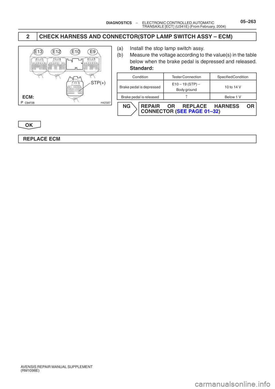
H42587
STP(+)
ECM:
E13E12E10E9
–
DIAGNOSTICS ELECTRONIC CONTROLLED AUTOMATIC
TRANSAXLE [ECT] (U341E) (From February, 2004)05–263
AVENSIS REPAIR MANUAL SUPPLEMENT
(RM1098E)
2 CHECK HARNESS AND CONNECTOR(STOP LAMP SWITCH ASSY – ECM)
(a) Install the stop lamp switch assy.
(b) Measure the voltage according to the value(s) in the table
below when the brake pedal is depressed and released.
Standard:
ConditionTester ConnectionSpecified Condition
Brake pedal is depressedE10 – 19 (STP) –
Body ground10 to 14 V
Brake pedal is released↑Below 1 V
NG REPAIR OR REPLACE HARNESS OR CONNEC TOR ( SEE PAGE 01–32 )
OK
REPLACE ECM
Page 5045 of 5135
![TOYOTA AVENSIS 2005 Service Repair Manual ���
C42920C53419
5 V/DIV
0.5 ms/DIV
G31763
ECM
NT+
NT– 26
34 B–O
B 2 1E12
E12 T4
Turbine Speed Sensor
5V
E1 05–258
– DIAGNOSTICSELECTRONIC CONTROLLED AUTOMATIC
TRANSAXLE [ECT] (U341E) (From F](/manual-img/14/57441/w960_57441-5044.png "TOYOTA AVENSIS 2005 Service Repair Manual ���
C42920C53419
5 V/DIV
0.5 ms/DIV
G31763
ECM
NT+
NT– 26
34 B–O
B 2 1E12
E12 T4
Turbine Speed Sensor
5V
E1 05–258
– DIAGNOSTICSELECTRONIC CONTROLLED AUTOMATIC
TRANSAXLE [ECT] (U341E) (From F")
���
C42920C53419
5 V/DIV
0.5 ms/DIV
G31763
ECM
NT+
NT– 26
34 B–O
B 2 1E12
E12 T4
Turbine Speed Sensor
5V
E1 05–258
– DIAGNOSTICSELECTRONIC CONTROLLED AUTOMATIC
TRANSAXLE [ECT] (U341E) (From February, 2004)
AVENSIS REPAIR MANUAL SUPPLEMENT
(RM1098E)
DTC P0717 TURBINE SPEED SENSOR CIRCUIT NO
SIGNAL
CIRCUIT DESCRIPTION
This sensor detects the rotation speed of the input turbine. By comparing the input turbine speed signal (NT)
with the vehicle speed sensor signal, the ECM detects the shift timing of the gears and appropriately controls
the engine torque and hydraulic pressure according to various conditions. Thus, providing smooth gear shift.
DTC No.DTC Detection ConditionTrouble Area
P0717
ECM detects conditions (a), (b) and (c) continuity for 5 sec. or
more: (1–trip detection logic)
(a) Vehicle speed: 50 km/h (31 mph) or more
(b) Park/neutral position switch (NSW, R and L) is OFF
(c) Speed sensor (NT): less than 300 rpm�Open or short in transmission revolution sensor NT (speed
sensor NT) circuit
�Transmission revolution sensor NT (speed sensor NT)
�ECM
Reference (Using an oscilloscope):
Check the waveform between the terminals NT+ and NT–
of the ECM connector.
Standard: Refer to the illustration.
TerminalNT+ – NT–
Tool setting5V/DIV, 0.5ms/DIV
Vehicle conditionVehicle speed 20 km/h (12 mph)
MONITOR DESCRIPTION
The input speed sensor detects the transmission input shaft speed. The ECM determines the gear shift tim-
ing based on a comparison of the input speed sensor (input shaft speed) with the output speed sensor (out-
put shaft speed).
When the output shaft speed is higher then the expected value and the input shaft speed is 300 rpm or less
while running with the shift in the D position, the ECM will conclude that there is malfunction of the input tur-
bine speed sensor (NT). The ECM will illuminate the MIL.
WIRING DIAGRAM
05KB1–02
Page 5046 of 5135
BR3795OK NG
C58536
1 2
Sensor Side:
(Connector Front View):
T4
– DIAGNOSTICSELECTRONIC CONTROLLED AUTOMATIC
TRANSAXLE [ECT] (U341E) (From February, 2004)05–259
AVENSIS REPAIR MANUAL SUPPLEMENT
(RM1098E)
INSPECTION PROCEDURE
1 INSPECT SPEED SENSOR INSTALLATION
(a) Check the speed sensor installation.
OK:
The installation bolt is tightened properly and there is
no clearance between the sensor and transaxle case.
NG REPLACE SPEED SENSOR(NT)
OK
2 INSPECT SPEED SENSOR(NT)
(a) Disconnect the speed sensor connector from the trans-
axle.
(b) Measure the resistance according to the value(s) in the
table below.
Standard:
Tester ConnectionSpecified Condition
20 �C (68 �F)
1 – 2560 to 680 Ω
NG REPLACE SPEED SENSOR(NT)
OK
Page 5047 of 5135
C95812
NT+
NT–
ECM:
E13
E12E10E9
05–260–
DIAGNOSTICS ELECTRONIC CONTROLLED AUTOMATIC
TRANSAXLE [ECT] (U341E) (From February, 2004)
AVENSIS REPAIR MANUAL SUPPLEMENT
(RM1098E)
3 CHECK HARNESS AND CONNECTOR(SPEED SENSOR – ECM)
(a) Connect the speed sensor connector.
(b) Disconnect the ECM connector.
(c) Measure the resistance according to the value(s) in the table below.
Standard:
Tester ConnectionSpecified Condition
20 �C (68 �F)
E12 – 26 (NT+) – E12 – 34 (NT–)560 to 680 Ω
(d) Measure the resistance according to the value(s) in the
table below.
Standard (Check for short):
Tester ConnectionSpecified Condition
E12 – 26 (NT+) – Body ground10 kΩ or higher
E12 – 34 (NT–) – Body ground↑
NG REPAIR OR REPLACE HARNESS OR
CONNEC TOR ( SEE PAGE 01–32 )
OK
REPLACE ECM
![TOYOTA AVENSIS 2005 Service Repair Manual BR3795OK NG
C58536
1 2
Sensor Side:
(Connector Front View):
T4
– DIAGNOSTICSELECTRONIC CONTROLLED AUTOMATIC
TRANSAXLE [ECT] (U341E) (From February, 2004)05–259
AVENSIS REPAIR MANUAL SUPPLEMENT
(RM](/manual-img/14/57441/w960_57441-5045.png "TOYOTA AVENSIS 2005 Service Repair Manual BR3795OK NG
C58536
1 2
Sensor Side:
(Connector Front View):
T4
– DIAGNOSTICSELECTRONIC CONTROLLED AUTOMATIC
TRANSAXLE [ECT] (U341E) (From February, 2004)05–259
AVENSIS REPAIR MANUAL SUPPLEMENT
(RM")
![TOYOTA AVENSIS 2005 Service Repair Manual C95812
NT+
NT–
ECM:
E13
E12E10E9
05–260–
DIAGNOSTICS ELECTRONIC CONTROLLED AUTOMATIC
TRANSAXLE [ECT] (U341E) (From February, 2004)
AVENSIS REPAIR MANUAL SUPPLEMENT
(RM1098E)
3 CHECK HARNESS AN](/manual-img/14/57441/w960_57441-5046.png "TOYOTA AVENSIS 2005 Service Repair Manual C95812
NT+
NT–
ECM:
E13
E12E10E9
05–260–
DIAGNOSTICS ELECTRONIC CONTROLLED AUTOMATIC
TRANSAXLE [ECT] (U341E) (From February, 2004)
AVENSIS REPAIR MANUAL SUPPLEMENT
(RM1098E)
3 CHECK HARNESS AN")