Page 2707 of 5135
4011Z±02
D30480
C81535
C91885
± AUTOMATIC TRANSMISSION / TRANSAUTOMATIC TRANSAXLE ASSY (U341E)
40±11
AVENSIS REPAIR MANUAL (RM1018E)
REPLACEMENT
1. REMOVE HOOD SUB±ASSY
2. REMOVE CYLINDER HEAD COVER NO.2
3. REMOVE RADIATOR SUPPORT OPENING COVER
4. REMOVE ENGINE ROOM COVER SIDE
5. REMOVE BATTERY
6. REMOVE BATTERY CARRIER
(a) Remove the 4 bolts and battery carrier and clamp.
7. REMOVE AIR CLEANER ASSY
8. SEPARATE TRANSMISSION CONTROL CABLE ASSY
(a) Remove the nut from the control shaft lever.
(b) Separate the control cable from the control shaft lever.
(c) Remove the clip and disconnect the control cable from
the control cable bracket.
9. REMOVE TRANSMISSION CONTROL CABLE CLAMP
(a) Disconnect the wire harness clamp and control cable
from the control cable clamp.
(b) Remove the bolt and control cable clamp.
Page 2708 of 5135

C91880
C80991
C91884
40±12
±
AUTOMATIC TRANSMISSION / TRANS AUTOMATIC TRANSAXLE ASSY (U341E)
AVENSIS REPAIR MANUAL (RM1018E)
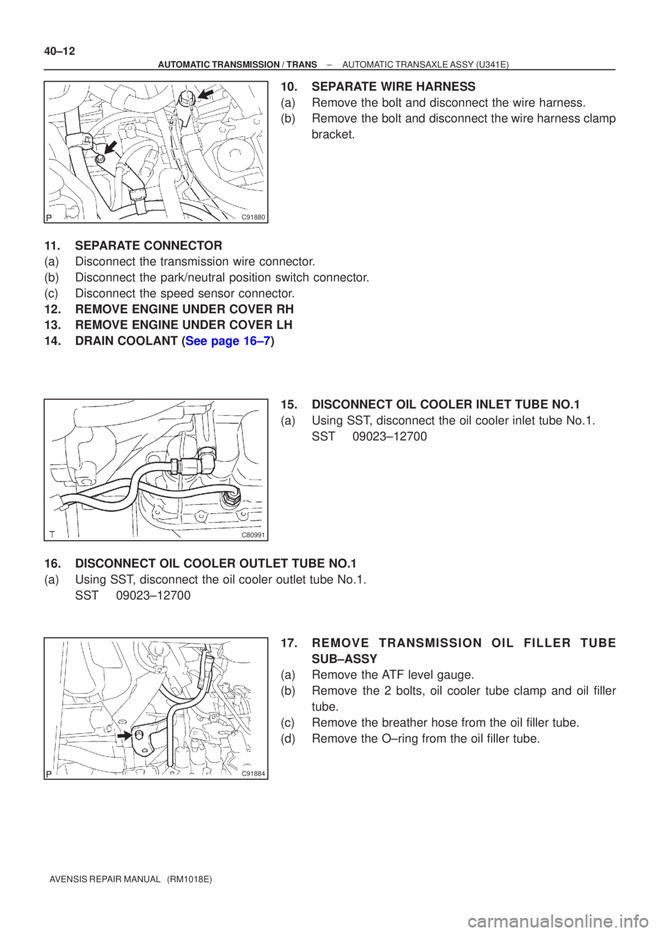
10. SEPARATE WIRE HARNESS
(a) Remove the bolt and disconnect the wire harness.
(b) Remove the bolt and disconnect the wire harness clamp bracket.
11. SEPARATE CONNECTOR
(a) Disconnect the transmission wire connector.
(b) Disconnect the park/neutral position switch connector.
(c) Disconnect the speed sensor connector.
12. REMOVE ENGINE UNDER COVER RH
13. REMOVE ENGINE UNDER COVER LH
14.DRAIN COOLANT (See page 16±7) 15. DISCONNECT OIL COOLER INLET TUBE NO.1
(a) Using SST, disconnect the oil cooler inlet tube No.1.SST 09023±12700
16. DISCONNECT OIL COOLER OUTLET TUBE NO.1
(a) Using SST, disconnect the oil cooler outlet tube No.1. SST 09023±12700
17. REMOVE TRANSMISSION OIL FILLER TUBESUB±ASSY
(a) Remove the ATF level gauge.
(b) Remove the 2 bolts, oil cooler tube clamp and oil filler
tube.
(c) Remove the breather hose from the oil filler tube.
(d) Remove the O±ring from the oil filler tube.
Page 2709 of 5135

C91882
C94723
D25372
±
AUTOMATIC TRANSMISSION / TRANS AUTOMATIC TRANSAXLE ASSY (U341E)
40±13
AVENSIS REPAIR MANUAL (RM1018E)
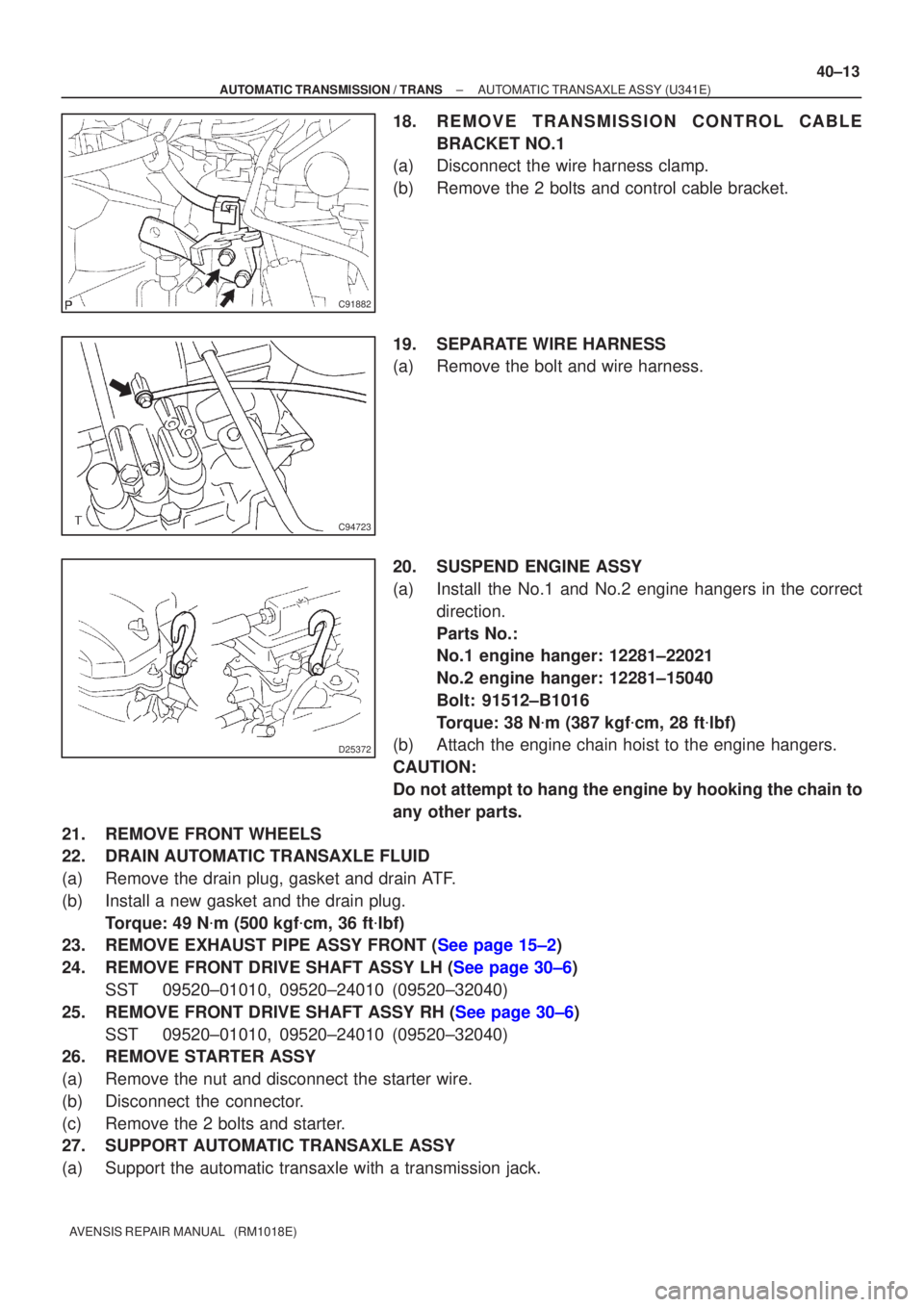
18. REMOVE TRANSMISSION CONTROL CABLE
BRACKET NO.1
(a) Disconnect the wire harness clamp.
(b) Remove the 2 bolts and control cable bracket.
19. SEPARATE WIRE HARNESS
(a) Remove the bolt and wire harness.
20. SUSPEND ENGINE ASSY
(a) Install the No.1 and No.2 engine hangers in the correct
direction.
Parts No.:
No.1 engine hanger: 12281±22021
No.2 engine hanger: 12281±15040
Bolt: 91512±B1016
Torque: 38 N �m (387 kgf �cm, 28 ft �lbf)
(b) Attach the engine chain hoist to the engine hangers.
CAUTION:
Do not attempt to hang the engine by hooking the chain to
any other parts.
21. REMOVE FRONT WHEELS
22. DRAIN AUTOMATIC TRANSAXLE FLUID
(a) Remove the drain plug, gasket and drain ATF.
(b) Install a new gasket and the drain plug. Torque: 49 N �m (500 kgf �cm, 36 ft �lbf)
23.REMOVE EXHAUST PIPE ASSY FRONT (See page 15±2)
24.REMOVE FRONT DRIVE SHAFT ASSY LH (See page 30±6)
SST 09520±01010, 09520±24010 (09520±32040)
25.REMOVE FRONT DRIVE SHAFT ASSY RH (See page 30±6) SST 09520±01010, 09520±24010 (09520±32040)
26. REMOVE STARTER ASSY
(a) Remove the nut and disconnect the starter wire.
(b) Disconnect the connector.
(c) Remove the 2 bolts and starter.
27. SUPPORT AUTOMATIC TRANSAXLE ASSY
(a) Support the automatic transaxle with a transmission jack.
Page 2710 of 5135
D31010
D30349
D30350
C87421
D25738
40±14
± AUTOMATIC TRANSMISSION / TRANSAUTOMATIC TRANSAXLE ASSY (U341E)
AVENSIS REPAIR MANUAL (RM1018E)
28. REMOVE TRANSVERSE ENGINE ENGINE
MOUNTING INSULATOR
(a) Remove the bolt and disconnect the wire harness clamp
bracket.
(b) Remove the 4 bolts, nut and engine mounting insulator
LH.
29. REMOVE TRANSVERSE ENGINE ENGINE
MOUNTING BRACKET
(a) Remove the 3 bolts and engine mounting bracket LH.
30. REMOVE TRANSVERSE ENGINE ENGINE
MOUNTING INSULATOR
(a) Remove the bolt from the engine mounting bracket RR.
(b) Remove the 3 nuts, bolt and engine mounting insulator
RR from the suspension member.
Page 2711 of 5135
C80166
C95354
D30347
D30348
± AUTOMATIC TRANSMISSION / TRANSAUTOMATIC TRANSAXLE ASSY (U341E)
40±15
AVENSIS REPAIR MANUAL (RM1018E)
31. REMOVE TRANSVERSE ENGINE ENGINE
MOUNTING INSULATOR
(a) Remove the bolt and nut from the engine mounting brack-
et FR.
32. REMOVE ENGINE MOUNTING MEMBER SUB±ASSY
CENTER
(a) Remove the 4 bolts and center member with engine
mounting insulator FR.
33. REMOVE TRANSVERSE ENGINE ENGINE
MOUNTING BRACKET
(a) Remove the 2 bolts and engine mounting bracket FR.
34. REMOVE TRANSVERSE ENGINE ENGINE
MOUNTING BRACKET
(a) Remove the 3 bolts and engine mounting bracket RR.
35. REMOVE FLYWHEEL HOUSING UNDER COVER
(a) Remove the flywheel housing under cover from the automatic transaxle.
Page 2712 of 5135
C91990
C67029
C63993
40±16
±
AUTOMATIC TRANSMISSION / TRANS AUTOMATIC TRANSAXLE ASSY (U341E)
AVENSIS REPAIR MANUAL (RM1018E)
36. REMOVE AUTOMATIC TRANSAXLE ASSY
(a) Turn the crankshaft to remove the 6 bolts while holding the crankshaft pulley bolt with a wrench.
(b) Remove the 6 bolts.
(c) Separate and remove the automatic transaxle.
37. REMOVE TORQUE CONVERTER CLUTCH ASSY
38.INSPECT TORQUE CONVERTER CLUTCH ASSY (See page 40±37) SST 09350±32014 (09351±32010, 09351±32020) 39. INSTALL TORQUE CONVERTER CLUTCH ASSY
(a) Install the torque converter clutch to the automatic trans-axle.
(b) Using vernier calipers, measure the dimension ºAº be- tween the trasaxle fitting part and the converter fitting part
of the drive plate.
Page 2713 of 5135

�
C65911
������D30888
A A
C
C B
B
C91990
D30348
± AUTOMATIC TRANSMISSION / TRANSAUTOMATIC TRANSAXLE ASSY (U341E)
40±17
AVENSIS REPAIR MANUAL (RM1018E)
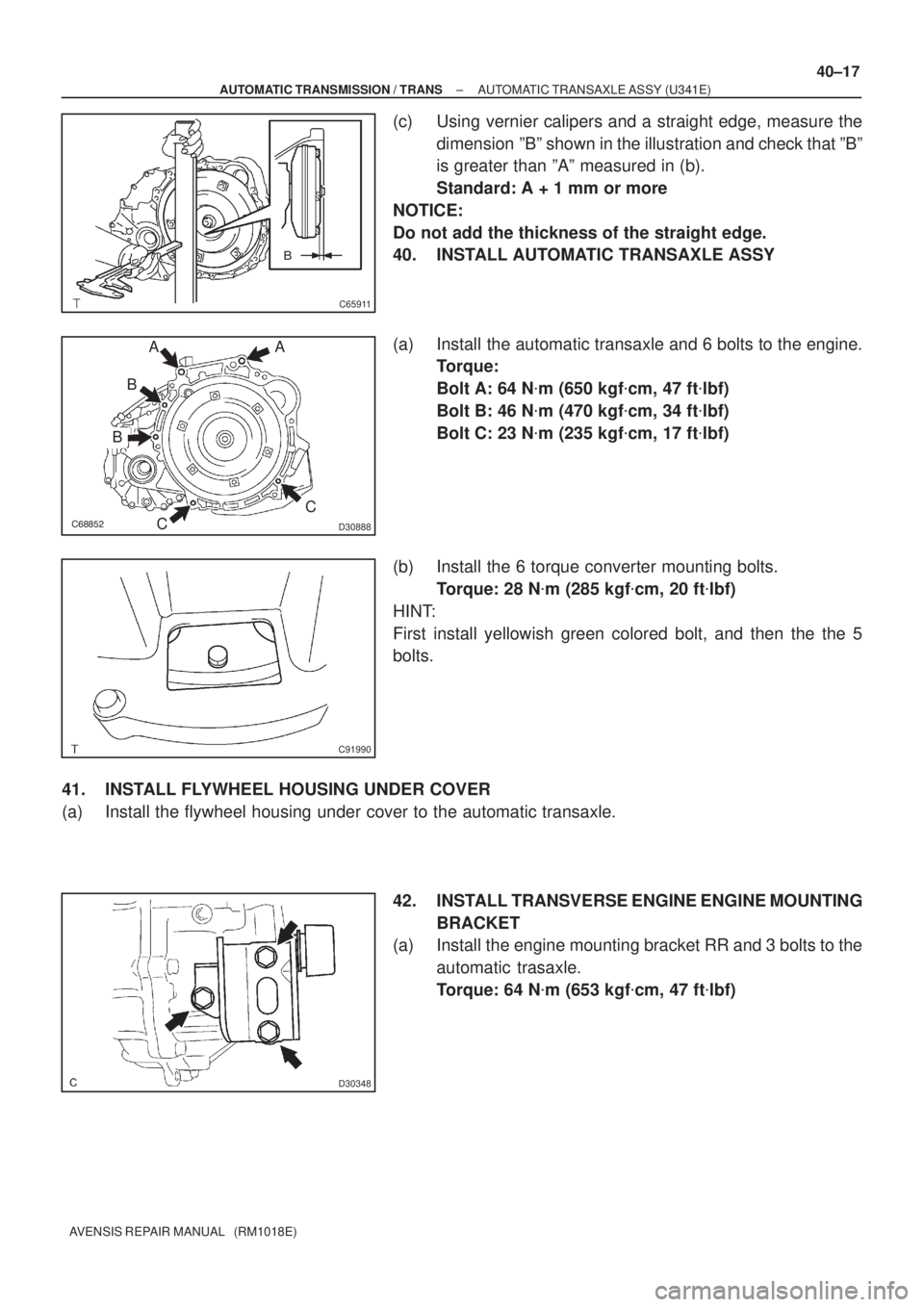
(c) Using vernier calipers and a straight edge, measure the
dimension ºBº shown in the illustration and check that ºBº
is greater than ºAº measured in (b).
Standard: A + 1 mm or more
NOTICE:
Do not add the thickness of the straight edge.
40. INSTALL AUTOMATIC TRANSAXLE ASSY
(a) Install the automatic transaxle and 6 bolts to the engine.
Torque:
Bolt A: 64 N�m (650 kgf�cm, 47 ft�lbf)
Bolt B: 46 N�m (470 kgf�cm, 34 ft�lbf)
Bolt C: 23 N�m (235 kgf�cm, 17 ft�lbf)
(b) Install the 6 torque converter mounting bolts.
Torque: 28 N�m (285 kgf�cm, 20 ft�lbf)
HINT:
First install yellowish green colored bolt, and then the the 5
bolts.
41. INSTALL FLYWHEEL HOUSING UNDER COVER
(a) Install the flywheel housing under cover to the automatic transaxle.
42. INSTALL TRANSVERSE ENGINE ENGINE MOUNTING
BRACKET
(a) Install the engine mounting bracket RR and 3 bolts to the
automatic trasaxle.
Torque: 64 N�m (653 kgf�cm, 47 ft�lbf)
Page 2714 of 5135

D30347
C95354C
B
A
A
������C80869
D25738
������C80870
40±18
± AUTOMATIC TRANSMISSION / TRANSAUTOMATIC TRANSAXLE ASSY (U341E)
AVENSIS REPAIR MANUAL (RM1018E)
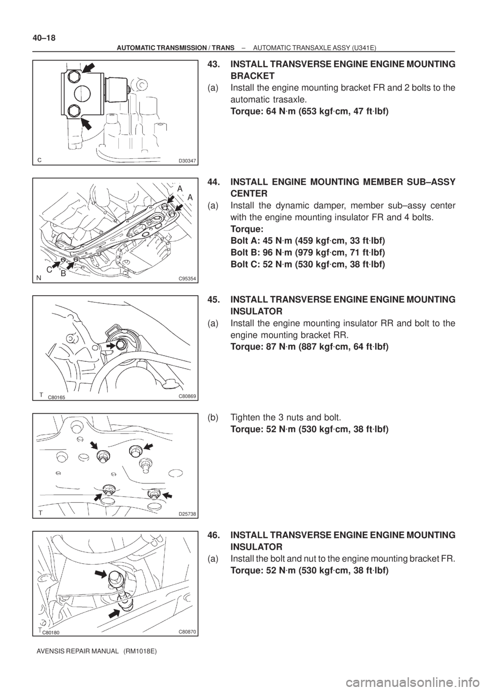
43. INSTALL TRANSVERSE ENGINE ENGINE MOUNTING
BRACKET
(a) Install the engine mounting bracket FR and 2 bolts to the
automatic trasaxle.
Torque: 64 N�m (653 kgf�cm, 47 ft�lbf)
44. INSTALL ENGINE MOUNTING MEMBER SUB±ASSY
CENTER
(a) Install the dynamic damper, member sub±assy center
with the engine mounting insulator FR and 4 bolts.
Torque:
Bolt A: 45 N�m (459 kgf�cm, 33 ft�lbf)
Bolt B: 96 N�m (979 kgf�cm, 71 ft�lbf)
Bolt C: 52 N�m (530 kgf�cm, 38 ft�lbf)
45. INSTALL TRANSVERSE ENGINE ENGINE MOUNTING
INSULATOR
(a) Install the engine mounting insulator RR and bolt to the
engine mounting bracket RR.
Torque: 87 N�m (887 kgf�cm, 64 ft�lbf)
(b) Tighten the 3 nuts and bolt.
Torque: 52 N�m (530 kgf�cm, 38 ft�lbf)
46. INSTALL TRANSVERSE ENGINE ENGINE MOUNTING
INSULATOR
(a) Install the bolt and nut to the engine mounting bracket FR.
Torque: 52 N�m (530 kgf�cm, 38 ft�lbf)