Page 3955 of 5135
A66060
PCV+E13PCV±
ECM Connector
A82559
PCV+ 10V/
Division
5 msec./Division
PCV±
500mV/
Division
±
DIAGNOSTICS ECD SYSTEM(1CD±FTV)
05±569
AVENSIS REPAIR MANUAL (RM1018E)
7INSPECT ECM(PCV VOLTAGE)
(a)Inspect using the oscilloscope.
(b)During cranking or idling, check the waveform between
the specified terminals of the E13 ECM connector.
Standard :
Symbols (Terminal No.)Specified condition
PCV+ (E13±2) ± PCV± (E13±1)Correct waveform is as shown
NGREPLACE ECM (See page 10±65)
OK
CHECK DTC OUTPUT RECUR (DTC P0088 AND/OR P1229 OUTPUT AGAIN)
HINT:
After clearing the DTC, drive the vehicle at 50 km/h (31 mph) for 5 minutes, and then confirm P0088 and/\
or
P1229 is not set again.
Page 3956 of 5135
A81016
ECM
STA
E97
B±Y
IJW±BJ12
B B
J13
J/C W±B 1 5
32 1AM2 2
B
B±R1
S51
S4
Starter
Battery7IK1
FL MAIN 3 3
Engine Room
R/B No. 3
B B 55
55 1
11A
BB±R
IE41
(LHD)IP11
(RHD)B±R
Engine
Room
R/B No. 1
Driver
Side R/B ST
Relay
2
DJ
9
DADriver
Side J/B B±R
B±RI13
Ignition Switch
4
5
AM2 ST2B±Y
B±Y
6
2ST 1
6 Fuse
Block
B±WB±Y B±YB±Y
J12
A C
J13C
J13
± DIAGNOSTICSECD SYSTEM (1CD±FTV)
05±691
AVENSIS REPAIR MANUAL (RM1018E)
STARTER SIGNAL CIRCUIT
CIRCUIT DESCRIPTION
HINT:
While the engine is being cranked, current flows from terminal ST2 of the ignition switch to the ST relay coil
and also current flows to terminal STA of the ECM (STA signal).
WIRING DIAGRAM
05B5Y±02
Page 3957 of 5135
05±692
±
DIAGNOSTICS ECD SYSTEM(1CD±FTV)
AVENSIS REPAIR MANUAL (RM1018E)
INSPECTION PROCEDURE
HINT:
This chart is on the premise that the engine is cranked normally. If the engine is not cranked, proceed to the
problem symptoms table on page 05±551.
1READ VALUE OF HAND±HELD TESTER(STA SIGNAL)
(a)Connect the hand±held tester to the DLC3.
(b)Turn the ignition switch ON and push the hand±held tester main switch \
ON.
(c)Select the item ºDIAGNOSIS / OBD/MOBD / DATA LIST / ALL / STARTER SIGº and read its value dis- played on the hand±held tester.
Standard:
Ignition Switch PositionONSTART
STARTER SIGOFFON
OKPROCEED TO NEXT CIRCUIT INSPECTION SHOWN ON PROBLEM SYMPTOMS TABLE
(See page 05±551)
NG
Page 3958 of 5135
A65748
STAE9
ECM Connector
A79097
Driver Side R/B
LHD
Starter Relay
A79098
Driver Side R/B
RHD
Starter Relay
±
DIAGNOSTICS ECD SYSTEM(1CD±FTV)
05±693
AVENSIS REPAIR MANUAL (RM1018E)
2INSPECT HARNESS AND CONNECTOR(ECM ± ST RELAY)
(a)Disconnect the E9 ECM connector.
(b)Remove the ST relay from the driver side R/B.
(c)Check for continuity between the wire harness side con-
nectors.
Standard (Check for open):
Symbols (Terminal No.)Specified condition
ST relay (1) ± STA (E9±7)Continuity
Standard (Check for short):
Symbols (Terminal No.)Specified condition
ST relay (1) or STA (E9±7) ± Body groundNo continuity
NGREPAIR OR REPLACE HARNESS OR CONNECTOR
OK
REPLACE ECM (See page 10±65)
Page 3959 of 5135

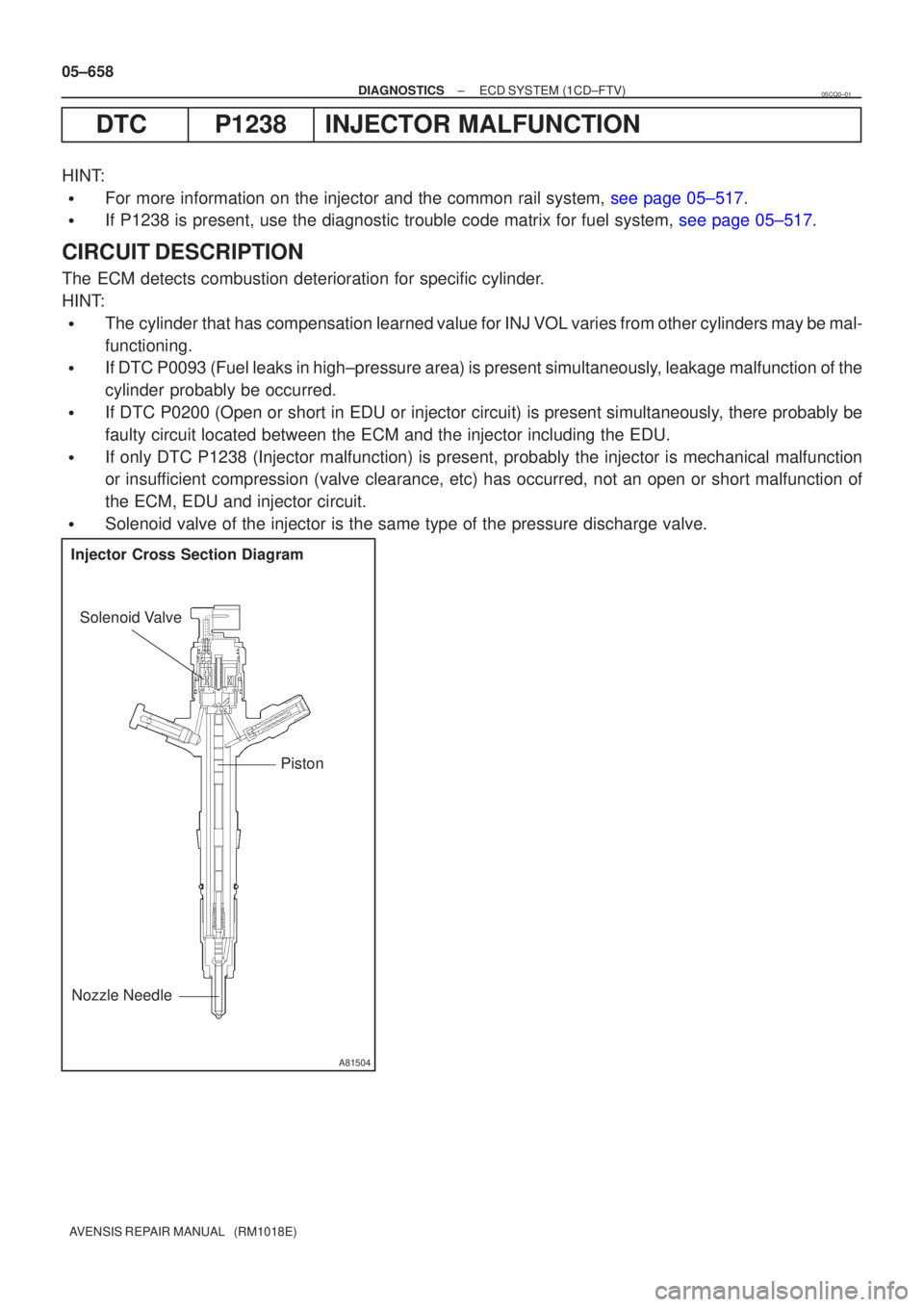
A81504
Injector Cross Section DiagramPiston
Solenoid Valve
Nozzle Needle
05±658
±
DIAGNOSTICS ECD SYSTEM(1CD±FTV)
AVENSIS REPAIR MANUAL (RM1018E)
DTCP1238INJECTOR MALFUNCTION
HINT:
�For more information on the injector and the common rail system, see page 05±517.
�If P1238 is present, use the diagnostic trouble code matrix for fuel sys\
tem, see page 05±517.
CIRCUIT DESCRIPTION
The ECM detects combustion deterioration for specific cylinder.
HINT:
�The cylinder that has compensation learned value for INJ VOL varies from other cylinders may be mal-
functioning.
�If DTC P0093 (Fuel leaks in high±pressure area) is present simultan\
eously, leakage malfunction of the
cylinder probably be occurred.
�If DTC P0200 (Open or short in EDU or injector circuit) is present sim\
ultaneously, there probably be
faulty circuit located between the ECM and the injector including the ED\
U.
�If only DTC P1238 (Injector malfunction) is present, probably the injector is \
mechanical malfunction
or insufficient compression (valve clearance, etc) has occurred, not an open o\
r short malfunction of
the ECM, EDU and injector circuit.
�Solenoid valve of the injector is the same type of the pressure discharg\
e valve.
05CQ0±01
Page 3960 of 5135

±
DIAGNOSTICS ECD SYSTEM(1CD±FTV)
05±659
AVENSIS REPAIR MANUAL (RM1018E)DTC No.
DTC Detection ConditionMain Trouble AreaRelated Trouble Area
P1238Engine speed variation is large when idling.
�
Injector
� EDU (P0200is set simultaneous-
ly)
� Open or short in engine wire
(P0200is set simultaneously)
� Connector connection (P0200is
set simultaneously)
� Compression pressure
� Valve clearance
�Valve timing
� ECM
HINT:
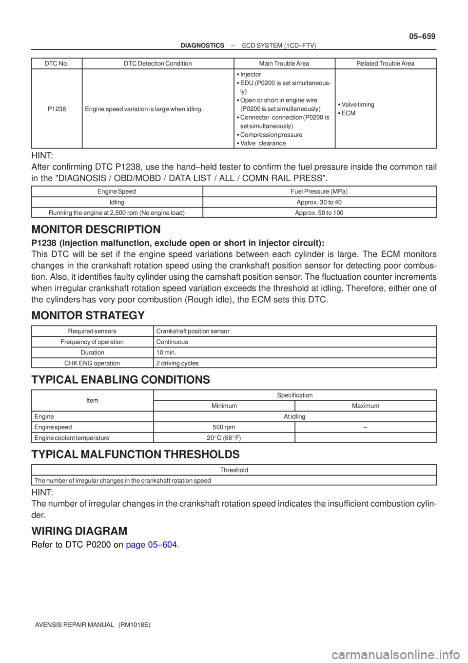
After confirming DTC P1238, use the hand±held tester to confirm the fuel pressure inside the common rail
in the ºDIAGNOSIS / OBD/MOBD / DATA LIST / ALL / COMN RAIL PRESSº.
Engine SpeedFuel Pressure (MPa)
IdlingApprox. 30 to 40
Running the engine at 2,500 rpm (No engine load)Approx. 50 to 100
MONITOR DESCRIPTION
P1238 (Injection malfunction, exclude open or short in injector circuit):
This DTC will be set if the engine speed variations between each cylinder is\
large. The ECM monitors
changes in the crankshaft rotation speed using the crankshaft position sensor f\
or detecting poor combus-
tion. Also, it identifies faulty cylinder using the camshaft position sensor. The fluctuation counter increments
when irregular crankshaft rotation speed variation exceeds the threshold at i\
dling. Therefore, either one of
the cylindershas very poor combustion (Rough idle), the ECM sets this DTC.
MONITOR STRATEGY
Required sensorsCrankshaft position sensor
Frequency of operationContinuous
Duration10 min.
CHK ENG operation2 driving cycles
TYPICAL ENABLING CONDITIONS
ItemSpecificationItemMinimumMaximum
EngineAt idling
Engine speed500 rpm±
Engine coolant temperature20 �C (68 �F)
TYPICAL MALFUNCTION THRESHOLDS
Threshold
The number of irregular changes in the crankshaft rotation speed
HINT:
The number of irregular changes in the crankshaft rotation speed indicat\
es the insufficient combustion cylin-
der.
WIRING DIAGRAM
Refer to DTC P0200 on page 05±604.
Page 3961 of 5135

05±660
±
DIAGNOSTICS ECD SYSTEM(1CD±FTV)
AVENSIS REPAIR MANUAL (RM1018E)
INSPECTION PROCEDURE
HINT:
�If DTCs other than P1238 are present simultaneously, first perform the troubleshooting for them.
�Read freeze frame data using �����\b��������
�� . Freeze frame data records the engine conditions
when a malfunction is detected. When troubleshooting, it is useful for d\
etermining whether the vehicle
was running or stopped, the engine was warmed up or not, etc. at the time o\
f the malfunction.
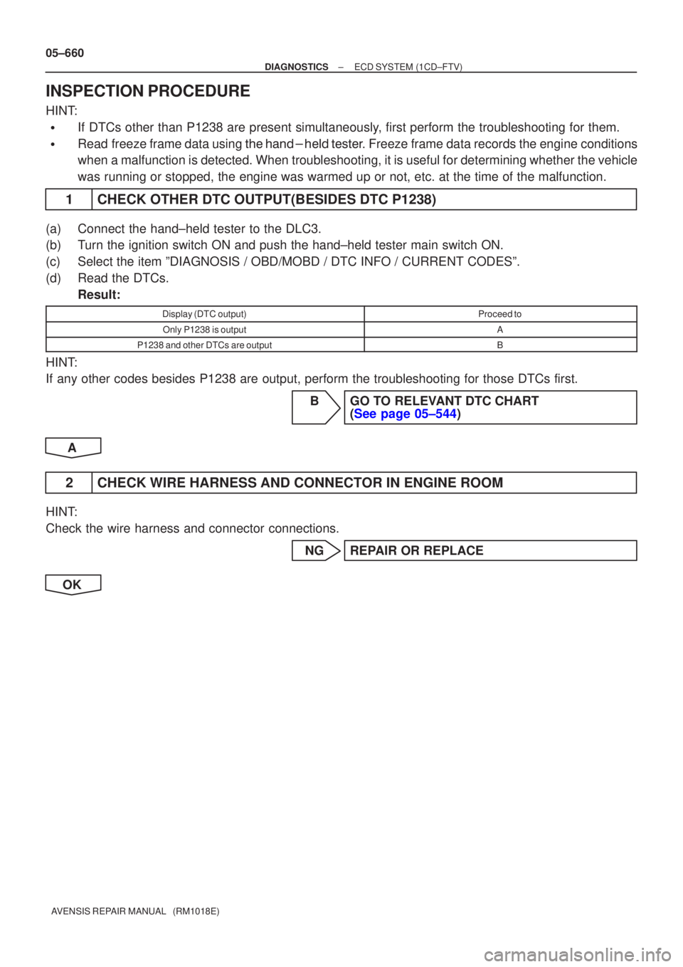
1CHECK OTHER DTC OUTPUT(BESIDES DTC P1238)
(a)Connect the hand±held tester to the DLC3.
(b)Turn the ignition switch ON and push the hand±held tester main switch \
ON.
(c)Select the item ºDIAGNOSIS / OBD/MOBD / DTC INFO / CURRENT CODESº.\
(d)Read the DTCs.
Result:
Display (DTC output)Proceed to
Only P1238 is outputA
P1238 and other DTCs are outputB
HINT:
If any other codes besides P1238 are output, perform the troubleshooting f\
or those DTCs first.
BGO TO RELEVANT DTC CHART(See page 05±544)
A
2 CHECK WIRE HARNESS AND CONNECTOR IN ENGINE ROOM
HINT:
Check the wire harness and connector connections. NG REPAIR OR REPLACE
OK
Page 3962 of 5135

±
DIAGNOSTICS ECD SYSTEM(1CD±FTV)
05±661
AVENSIS REPAIR MANUAL (RM1018E)
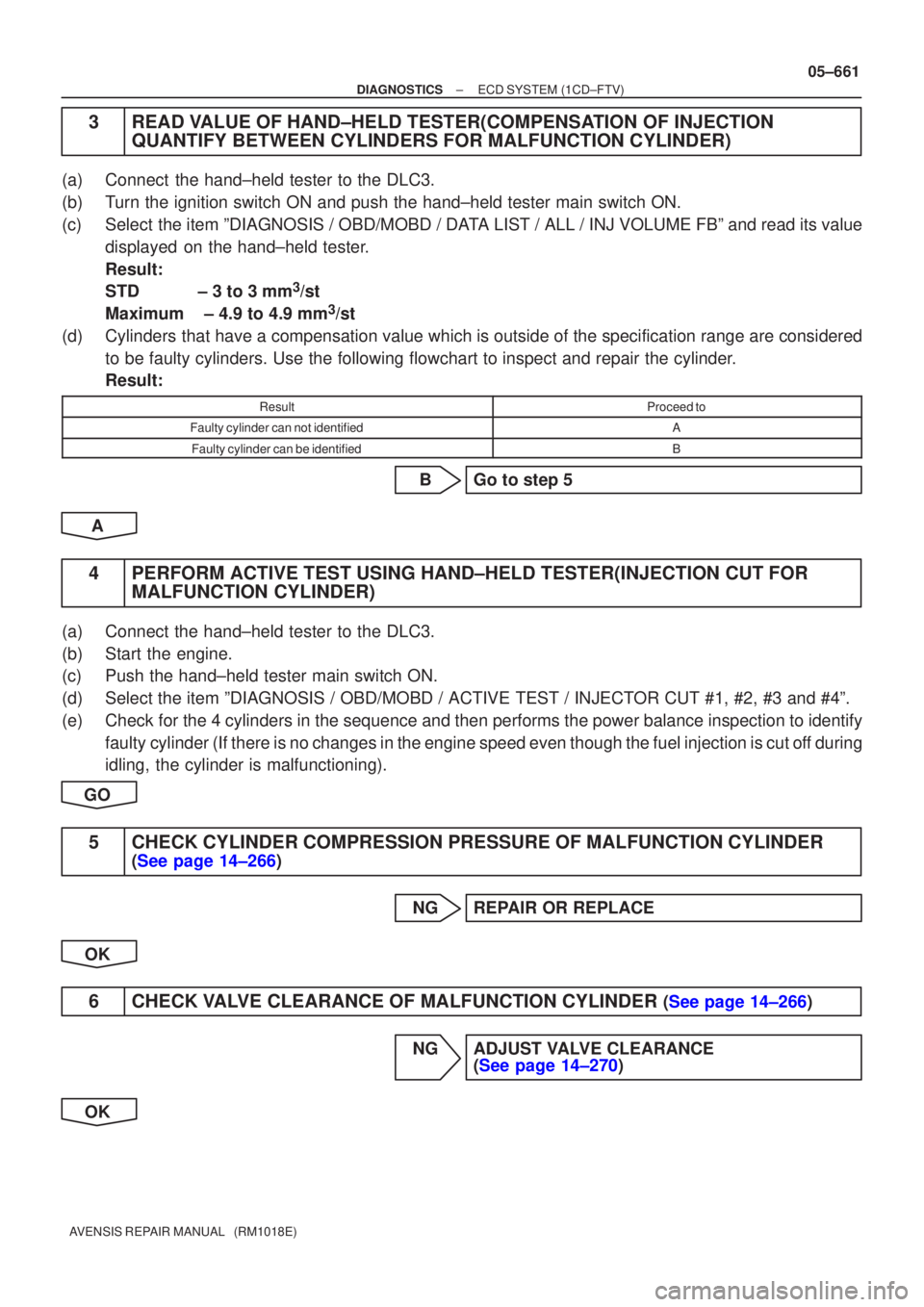
3READ VALUE OF HAND±HELD TESTER(COMPENSATION OF INJECTION
QUANTIFY BETWEEN CYLINDERS FOR MALFUNCTION CYLINDER)
(a)Connect the hand±held tester to the DLC3.
(b)Turn the ignition switch ON and push the hand±held tester main switch \
ON.
(c)Select the item ºDIAGNOSIS / OBD/MOBD / DATA LIST / ALL / INJ VOLUME FBº and read its value
displayed on the hand±held tester.
Result:
STD ± 3 to 3 mm
3/st
Maximum ± 4.9 to 4.9 mm
3/st
(d)Cylinders that have a compensation value which is outside of the specification ra\
nge are considered to be faulty cylinders. Use the following flowchart to inspect and repair \
the cylinder.
Result:
ResultProceed to
Faulty cylinder can not identifiedA
Faulty cylinder can be identifiedB
BGo to step 5
A
4PERFORM ACTIVE TEST USING HAND±HELD TESTER(INJECTION CUT FOR MALFUNCTION CYLINDER)
(a)Connect the hand±held tester to the DLC3.
(b)Start the engine.
(c)Push the hand±held tester main switch ON.
(d)Select the item ºDIAGNOSIS / OBD/MOBD / ACTIVE TEST / INJECTOR CUT #1, #2, #3 and #4º.
(e)Check for the 4 cylinders in the sequence and then performs the power balance\
inspection to identify
faulty cylinder (If there is no changes in the engine speed even though the f\
uel injection is cut off during
idling, the cylinder is malfunctioning).
GO
5CHECK CYLINDER COMPRESSION PRESSURE OF MALFUNCTION CYLINDER
(See page 14±266)
NG REPAIR OR REPLACE
OK
6CHECK VALVE CLEARANCE OF MALFUNCTION CYLINDER (See page 14±266)
NG ADJUST VALVE CLEARANCE (See page 14±270)
OK