2005 SUZUKI JIMNY check engine
[x] Cancel search: check enginePage 122 of 687

Downloaded from www.Manualslib.com manuals search engine STEERING GEAR BOX (MANUAL TYPE) AND LINKAGE 3B-1
6F1
6F2
6G
6H
3B
7C1
7D
7E
7D
7E
7F
8A
8B
8C
8D
8E
9
10
10A
10B
SECTION 3B
STEERING GEAR BOX (MANUAL TYPE)
AND LINKAGE
CONTENTS
General Description ....................................... 3B-2
Diagnosis ........................................................ 3B-3
Diagnosis Table ........................................... 3B-3
Steering Wheel Play Check ......................... 3B-3
Tie Rod And Drag Rod Check ...................... 3B-3
Steering Gear Box Oil Level Check ............. 3B-4
Adjustment of Worm Shaft Starting Torque . 3B-4On-Vehicle Service ........................................ 3B-6
Steering Gear Box ....................................... 3B-6
Tie Rod And Drag Rod................................. 3B-8
Tightening Torque Specifications .............. 3B-10
Required Service Material ........................... 3B-10
Special Tools ................................................ 3B-10 WARNING:
For vehicles equipped with Supplemental Restraint (Air Bag) System
Service on and around the air bag system components or wiring must be performed only by an
authorized SUZUKI dealer. Refer to “Air Bag System Components and Wiring Location View” under
“General Description” in air bag system section in order to confirm whether you are performing ser-
vice on or near the air bag system components or wiring. Please observe all WARNINGS and “Ser-
vice Precautions” under “On-Vehicle Service” in air bag system section before performing service
on or around the air bag system components or wiring. Failure to follow WARNINGS could result in
unintentional activation of the system or could render the system inoperative. Either of these two
conditions may result in severe injury.
Technical service work must be started at least 90 seconds after the ignition switch is turned to the
“LOCK” position and negative cable is disconnected from the battery. Otherwise, the system may
be activated by reserve energy in the Sensing and Diagnostic Module (SDM)
NOTE:
All steering gear fasteners are important attaching parts in that they could affect the performance of
vital parts and systems, and/or could result in major repair expense. They must be replaced with one
of the same part number or with an equivalent part if replacement becomes necessary. Do not use a
replacement part of lesser quality or substitute design. Torque values must be used as specified dur-
ing reassembly to assure proper retention of these parts.
Page 124 of 687

Downloaded from www.Manualslib.com manuals search engine STEERING GEAR BOX (MANUAL TYPE) AND LINKAGE 3B-3
Diagnosis
Diagnosis Table
Refer to “Diagnosis Table” in Section 3.
Steering Wheel Play Check
Check steering wheel for play and rattle, holding vehicle in
straight forward condition on ground.
Steering wheel play
“a” : 10 – 30 mm (0.4 – 1.2 in.)
If play is not within specification, inspect for the following. If found
defective, replace.
Wear of tie rod end ball stud.
Wear of king pin bearing
Wear of steering shaft joint.
Loosely install or joined parts.
Wear of steering rack / sector gear.
Tie Rod And Drag Rod Check
Inspect deformation or damage. Replace any defective part.
INSPECTION
1) Inspect for play in tie rod end ball joint (1). If found defective,
replace.
2) Inspect boot (2) for tear. If even a small tear is noted, replace
with new one.
Page 125 of 687

Downloaded from www.Manualslib.com manuals search engine 3B-4 STEERING GEAR BOX (MANUAL TYPE) AND LINKAGE
Steering Gear Box Oil Level Check
Oil surface should be up to the level as shown in figure. If not, add
prescribed gear oil, SAE 90.
Steering gear box oil level
“a” : 23 mm (0.91 in.)
Apply sealant to thread parts of breathing plug and tighten breath-
ing plug to specified torque.
(A) : Sealant 99000-31110
Tightening torque
Breathing plug
(a) : 4 N·m (0.4 kg-m, 3.0 lb-ft)
Adjustment of Worm Shaft Starting Torque
Steering gear box has adjusting bolt (1) which gives preload to
sector shaft.
Special tool
(A) : 09944-18211
MAKE ADJUSTMENT ACCORDING TO FOLLOWING PRO-
CEDURE.
1) Check worm shaft (1) to ensure that it is free from thrust
play.
2) Position pitman arm (2) in nearly parallel with worm shaft (1)
as shown. (With pitman arm (2) in this position, front wheels
are in straightforward state.)
Page 126 of 687

Downloaded from www.Manualslib.com manuals search engine STEERING GEAR BOX (MANUAL TYPE) AND LINKAGE 3B-5
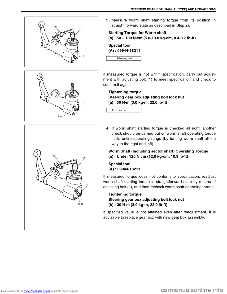
3) Measure worm shaft starting torque from its position in
straight forward state as described in Step 2).
Starting Torque for Worm shaft
(a) : 50 – 100 N·cm (5.0-10.0 kg-cm, 0.4-0.7 lb-ft)
Special tool
(A) : 09944-18211
If measured torque is not within specification, carry out adjust-
ment with adjusting bolt (1) to meet specification and check to
confirm it again.
Tightening torque
Steering gear box adjusting bolt lock nut
(a) : 30 N·m (3.0 kg-m, 22.0 lb-ft)
4) If worm shaft starting torque is checked all right, another
check should be carried out on worm shaft operating torque
in its entire operating range (by turning worm shaft all the
way to the right and left).
Worm Shaft (Including sector shaft) Operating Torque
(a) : Under 120 N·cm (12.0 kg-cm, 10.9 lb-ft)
Special tool
(A) : 09944-18211
If measured torque does not conform to specification, readjust
worm shaft starting torque in straightforward state by means of
adjusting bolt (1), and then recheck worm shaft operating torque.
Tightening torque
Steering gear box adjusting bolt lock nut
(b) : 30 N·m (3.0 kg-m, 22.0 lb-ft)
If specified value is not attained even after readjustment, it is
advisable to replace gear box with new gear box assembly.
1. Adjusting bolt
2. Lock nut
Page 130 of 687

Downloaded from www.Manualslib.com manuals search engine STEERING GEAR BOX (MANUAL TYPE) AND LINKAGE 3B-9
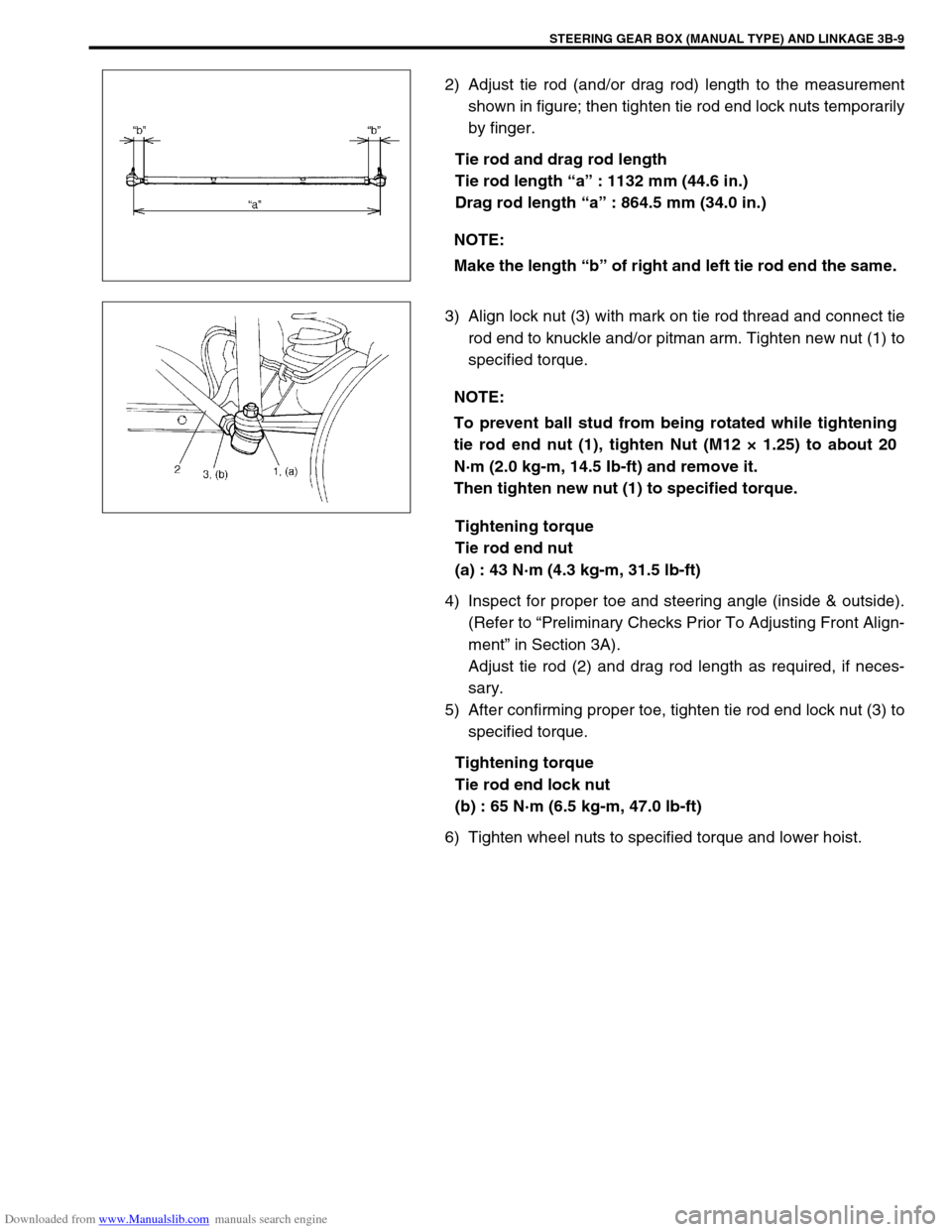
2) Adjust tie rod (and/or drag rod) length to the measurement
shown in figure; then tighten tie rod end lock nuts temporarily
by finger.
Tie rod and drag rod length
Tie rod length “a” : 1132 mm (44.6 in.)
Drag rod length “a” : 864.5 mm (34.0 in.)
3) Align lock nut (3) with mark on tie rod thread and connect tie
rod end to knuckle and/or pitman arm. Tighten new nut (1) to
specified torque.
Tightening torque
Tie rod end nut
(a) : 43 N·m (4.3 kg-m, 31.5 lb-ft)
4) Inspect for proper toe and steering angle (inside & outside).
(Refer to “Preliminary Checks Prior To Adjusting Front Align-
ment” in Section 3A).
Adjust tie rod (2) and drag rod length as required, if neces-
sary.
5) After confirming proper toe, tighten tie rod end lock nut (3) to
specified torque.
Tightening torque
Tie rod end lock nut
(b) : 65 N·m (6.5 kg-m, 47.0 lb-ft)
6) Tighten wheel nuts to specified torque and lower hoist.NOTE:
Make the length “b” of right and left tie rod end the same.
NOTE:
To prevent ball stud from being rotated while tightening
tie rod end nut (1), tighten Nut (M12 × 1.25) to about 20
N·m (2.0 kg-m, 14.5 Ib-ft) and remove it.
Then tighten new nut (1) to specified torque.
Page 131 of 687

Downloaded from www.Manualslib.com manuals search engine 3B-10 STEERING GEAR BOX (MANUAL TYPE) AND LINKAGE
Tightening Torque Specifications
Required Service Material
Special Tools
Fastening partTightening torque
Nm kg-m lb-ft
Steering gear box oil plug 4 0.4 3.0
Steering gear box adjusting bolt lock nut 30 3.0 22.0
Pitman arm mounting nut 135 13.5 98.0
Steering shaft joint bolt 25 2.5 18.0
Steering gear box nuts and bolt 80 8.0 58.0
Tie rod end nut and drag rod end nut
(knuckle side)43 4.3 31.5
Wheel nut 95 9.5 69.0
Tie rod end lock nut 65 6.5 47.0
Drag rod end nut (pitman arm side) 50 5.0 36.5
MaterialRecommended SUZUKI product
(Part Number)Use
Sealant SUZUKI BOND NO. 1215
(99000-31110)Thread of oil breathing plug
09913-65210 09944-18211
Tie-rod end remover Pinion torque checking socket
Page 132 of 687

Downloaded from www.Manualslib.com manuals search engine POWER STEERING (P/S) SYSTEM (If equipped) 3B1-1
6F1
6F2
6G
6H
6K
3B1
7D
7E
7F
7E
7F
8A
8B
8C
8D
8E
9
10
10A
10B
SECTION 3B1
POWER STEERING (P/S) SYSTEM
(If equipped)
CONTENTS
General Description ......................................3B1-2
Diagnosis .......................................................3B1-3
Diagnosis Table .......................................... 3B1-3
Steering Wheel Play Check ........................ 3B1-5
Steering Force Check ................................. 3B1-5
Power Steering Belt Check ......................... 3B1-6
Power Steering Belt Tension Adjustment .... 3B1-6
Power Steering Fluid Level Check .............. 3B1-6
Idle-Up System Check ................................ 3B1-7
Power Steering Fluid Leakage Check ......... 3B1-7Air Bleeding Procedure ............................... 3B1-8
Hydraulic Pressure In P/S Circuit Check .. 3B1-10
On-Vehicle Service ..................................... 3B1-12
Power Steering Belt .................................. 3B1-12
Power Steering (P/S) Pump ...................... 3B1-12
Power Steering (P/S) Gear Box ................ 3B1-18
Tightening Torque Specifications ............. 3B1-21
Required Service Materials ........................ 3B1-21
Special Tools ............................................... 3B1-21 WARNING:
For vehicles equipped with Supplemental Restraint (Air Bag) System :
Service on and around the air bag system components or wiring must be performed only by an
authorized SUZUKI dealer. Refer to “Air Bag System Components and Wiring Location View” under
“General Description” in air bag system section in order to confirm whether you are performing ser-
vice on or near the air bag system components or wiring. Please observe all WARNINGS and “Ser-
vice Precautions” under “On-Vehicle Service” in air bag system section before performing service
on or around the air bag system components or wiring. Failure to follow WARNINGS could result in
unintentional activation of the system or could render the system inoperative. Either of these two
conditions may result in severe injury.
Technical service work must be started at least 90 seconds after the ignition switch is turned to the
“LOCK” position and negative cable is disconnected from the battery. Otherwise, the system may
be activated by reserve energy in the Sensing and Diagnostic Module (SDM).
NOTE:
All steering gear fasteners are important attaching parts in that they could affect the performance of
vital parts and systems, and/or could result in major repair expense. They must be replaced with one
of the same part number or with an equivalent part if replacement becomes necessary. Do not use a
replacement part of lesser quality or substitute design. Torque values must be used as specified dur-
ing reassembly to assure proper retention of these parts.
Page 134 of 687

Downloaded from www.Manualslib.com manuals search engine POWER STEERING (P/S) SYSTEM (If equipped) 3B1-3
Diagnosis
Diagnosis Table
Condition Possible Cause Correction
Steering wheel feels
heavy
(at low speed)Fluid deteriorated, low viscosity, different type of
fluid mixedChange fluid.
Pipes or hoses deformed, air entering through
jointCorrect or replace.
Insufficient air bleeding from piping Bleed air.
Belt worn, lacking in tension Adjust belt tension or replace belt
as necessary.
Tire inflation pressure too low Inflate tire.
Wheel alignment out of adjustment Adjust front wheel alignment.
Steering wheel installed improperly (twisted) Install steering wheel correctly.
Hydraulic pressure failing to rise (See NOTE
“A”.)Replace P/S pump.
Slow hydraulic pressure rise (See NOTE “A”.)
Steering wheel feels
heavy momentarily
when turning it to the
left or right.Air drawn in due to insufficient amount of fluid Add fluid and bleed air.
Slipping belt Adjust belt tension or replace belt
as necessary.
No idle-up (See NOTE
“B”.)Defective pressure switch Replace pressure switch
(terminal set).
NOTE:
“A” : Be sure to warm up engine fully before performing this check. Pump vanes are sometimes
hard to come out where temperature is low.
“B” : Acceptable if idling speed does not drop.
Condition Possible Cause Correction
Steering wheel returns
slowly from turns.
(See NOTE “C”.)Dust or foreign object mixed in fluid Change fluid.
Deformed pipes or hoses Correct or replace.
Steering column installed improperly Install correctly.
Wheel alignment maladjusted Adjust.
Linkage or joints not operating smoothly Correct.
Vehicle pulls to one
side during straight
driving.Low or uneven tire inflation pressure Inflate tire (s) as necessary.
Wheel alignment maladjusted Adjust.
Defective spool valve Replace gear box assembly.
Steering wheel play is
large and vehicle wan-
ders.Loose steering shaft nut Retighten.
Loose linkage or joint Retighten.
Loose gear box fixing bolt Retighten.
Front wheel bearing worn Replace.
Fluid leakage
Loose joints of hydraulic pressure pipes and
hosesRetighten.
Deformed or damaged pipes or hoses Correct or replace.
Gear box Replace gear box assembly.