Page 92 of 687

Downloaded from www.Manualslib.com manuals search engine AIR CONDITIONING (OPTIONAL) 1B-31
Condenser Assembly
INSPECTION
Check the following.
Check clog of condenser fins.
If, any clogs are found, condenser fins should be washed
with water, and should be dried with compressed air.
Check condenser fins for leakage and breakage.
If any defects are found, repair or replace condenser.
Check condenser fittings for leakage.
If any defects are found, repair or replace condenser.
REMOVAL
1) Disconnect negative (–) cable at battery.
2) Recover refrigerant from A/C system by referring to “Recov-
ery” in this section.
3) Remove front bumper referring to “Front Bumper” in Section
8.
4) Disconnect A/C condenser cooling fan motor and dual pres-
sure switch connectors.
5) Remove radiator mounting bolts.
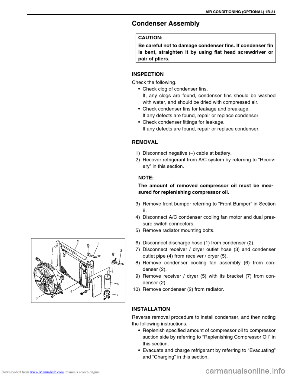
6) Disconnect discharge hose (1) from condenser (2).
7) Disconnect receiver / dryer outlet hose (3) and condenser
outlet pipe (4) from receiver / dryer (5).
8) Remove condenser cooling fan assembly (6) from con-
denser (2).
9) Remove receiver / dryer (5) with its bracket (7) from con-
denser (2).
10) Remove condenser (2) from radiator.
INSTALLATION
Reverse removal procedure to install condenser, and then noting
the following instructions.
Replenish specified amount of compressor oil to compressor
suction side by referring to “Replenishing Compressor Oil” in
this section.
Evacuate and charge refrigerant by referring to “Evacuating”
and “Charging” in this section. CAUTION:
Be careful not to damage condenser fins. If condenser fin
is bent, straighten it by using flat head screwdriver or
pair of pliers.
NOTE:
The amount of removed compressor oil must be mea-
sured for replenishing compressor oil.
Page 94 of 687
Downloaded from www.Manualslib.com manuals search engine AIR CONDITIONING (OPTIONAL) 1B-33
Condenser Cooling Fan Assembly
ASSEMBLY
INSPECTION
1) Check continuity between each two terminals about the con-
denser cooling fan motor (1).
If check results are no continuity, replace condenser cooling
fan motor.
2) Connect battery to condenser cooling fan motor as shown in
figure, then check that the condenser cooling fan motor
operates smoothly.
Reference current of condenser cooling fan motor
approximately 7.5 A at 12 V
REMOVAL
1) Remove front bumper.
2) Disconnect condenser cooling fan motor connector (1).
3) Remove radiator mounting bolts.
4) Remove condenser cooling fan assembly (2) from con-
denser (3).
INSTALLATION
Reverse removal procedure for installation.CAUTION:
Be careful not to damage condenser fins. If condenser fin
is bent, straighten condenser fin by using flat head
screwdriver or pair of pliers.
Page 96 of 687
Downloaded from www.Manualslib.com manuals search engine AIR CONDITIONING (OPTIONAL) 1B-35
3) Drain engine coolant and disconnect heater hoses (1) from
heater unit.
4) Disable air bag system referring to “Disabling Air Bag Sys-
tem” in Section 10B (if equipped).
5) Remove attaching bolt (1).
6) Disconnect suction hose (2) and receiver / dryer outlet pipe
(3) from expansion valve (4).
7) Remove instrument panel referring to “Instrument Panel” in
Section 9.
8) Remove cooling unit (1) with heater unit (2) from vehicle
body.
9) Remove cooling unit (1) from heater unit (2).
INSPECTION
Check the following.
Check clog of A/C evaporator fins.
If any clogs are found, A/C evaporator fins should be
washed with water, and should be dried with compressed
air.
Check A/C evaporator fins for leakage and breakage.
If any defects are found, repair or replace A/C evaporator.
Check A/C evaporator fittings for leakage.
If any defects are found, repair or replace A/C evaporator.
Page 98 of 687
Downloaded from www.Manualslib.com manuals search engine AIR CONDITIONING (OPTIONAL) 1B-37
A/C Evaporator Thermistor (A/C Evaporator
Temperature Sensor)
INSPECTION
Check resistance between terminals for A/C evaporator ther-
mistor (1).
If check results are as not specified, replace thermistor.
A/C evaporator temperature sensor resistance
Expansion Valve
INSPECTION
Refer to “Performance Diagnosis” in this section.
REMOVAL
1) Disconnect negative (–) cable at battery.
2) Recover refrigerant from A/C system by referring to
“Recover” in this section.
3) Remove attaching bolt (1).
4) Remove suction hose (2) and receiver dryer outlet pipe (3)
from expansion valve (4).
5) Remove expansion valve (4).Sensor Temperature (°C (°F)) Resistance (k
Ω)
0 (32) 6.4 – 7.0
25 (77) 1.8 – 2.2
NOTE:
When A/C evaporator thermistor (1) removed, its should
be reinstalled in original position.
NOTE:
The amount of removed compressor oil must be mea-
sured for replenishing compressor oil.
Page 99 of 687

Downloaded from www.Manualslib.com manuals search engine 1B-38 AIR CONDITIONING (OPTIONAL)
INSTALLATION
Reverse removal procedure for installation, and then note the fol-
lowing instructions.
Replenish specified amount of compressor oil to compressor
suction side by referring to “Replenishing Compressor Oil” in
this section.
Evacuate and charge refrigerant by referring to “Evacuation”
and “Charging” in this section.
Dual Pressure Switch
INSPECTION
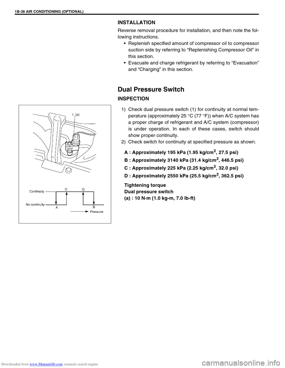
1) Check dual pressure switch (1) for continuity at normal tem-
perature (approximately 25 °C (77 °F)) when A/C system has
a proper charge of refrigerant and A/C system (compressor)
is under operation. In each of these cases, switch should
show proper continuity.
2) Check switch for continuity at specified pressure as shown.
A : Approximately 195 kPa (1.95 kg/cm
2, 27.5 psi)
B : Approximately 3140 kPa (31.4 kg/cm
2, 446.5 psi)
C : Approximately 225 kPa (2.25 kg/cm
2, 32.0 psi)
D : Approximately 2550 kPa (25.5 kg/cm
2, 362.5 psi)
Tightening torque
Dual pressure switch
(a) : 10 N·m (1.0 kg-m, 7.0 lb-ft)
Page 100 of 687

Downloaded from www.Manualslib.com manuals search engine AIR CONDITIONING (OPTIONAL) 1B-39
A/C Switch
REMOVAL AND INSTALLATION
Refer to “Heater Control Lever Assembly” in Section 1A.
INSPECTION
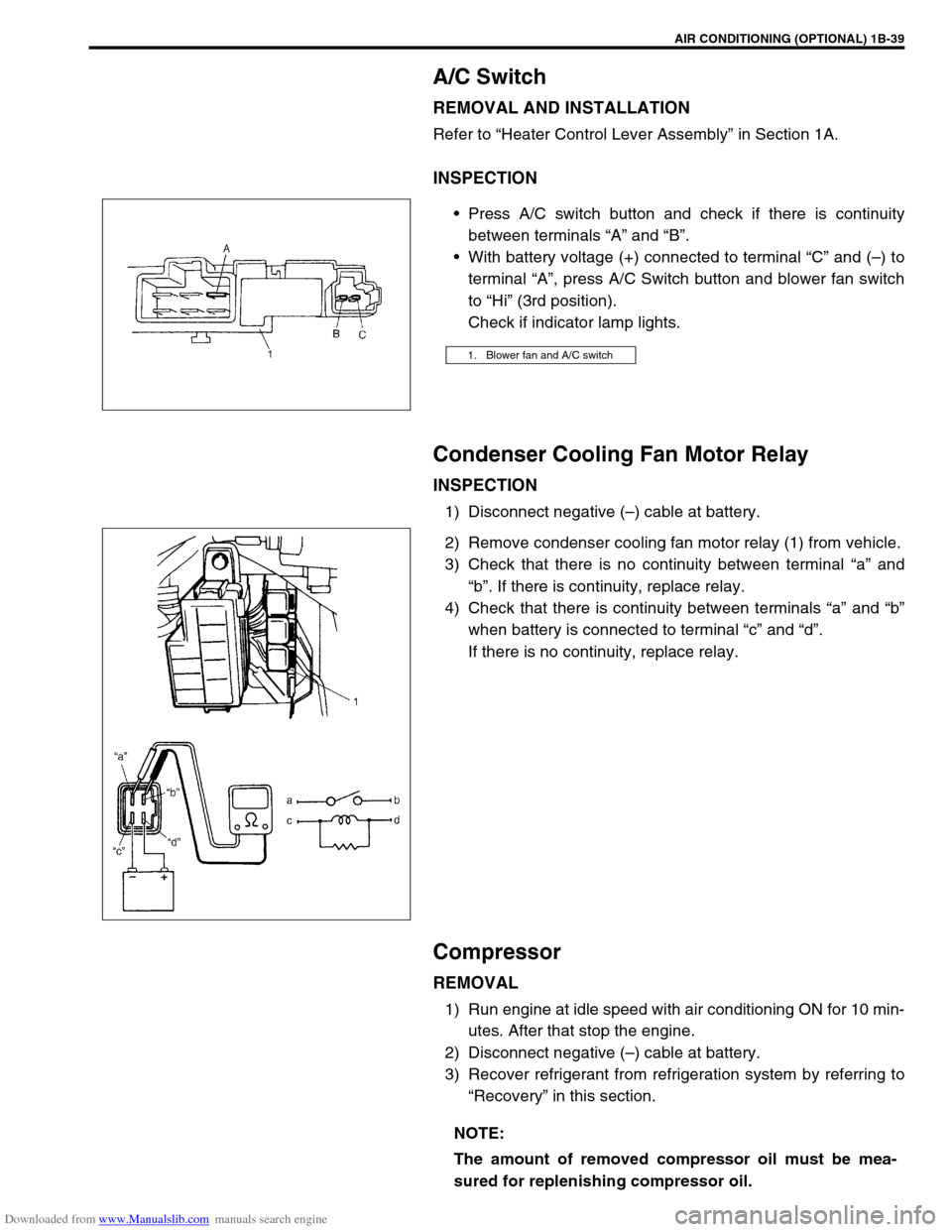
Press A/C switch button and check if there is continuity
between terminals “A” and “B”.
With battery voltage (+) connected to terminal “C” and (–) to
terminal “A”, press A/C Switch button and blower fan switch
to “Hi” (3rd position).
Check if indicator lamp lights.
Condenser Cooling Fan Motor Relay
INSPECTION
1) Disconnect negative (–) cable at battery.
2) Remove condenser cooling fan motor relay (1) from vehicle.
3) Check that there is no continuity between terminal “a” and
“b”. If there is continuity, replace relay.
4) Check that there is continuity between terminals “a” and “b”
when battery is connected to terminal “c” and “d”.
If there is no continuity, replace relay.
Compressor
REMOVAL
1) Run engine at idle speed with air conditioning ON for 10 min-
utes. After that stop the engine.
2) Disconnect negative (–) cable at battery.
3) Recover refrigerant from refrigeration system by referring to
“Recovery” in this section.
1. Blower fan and A/C switch
NOTE:
The amount of removed compressor oil must be mea-
sured for replenishing compressor oil.
Page 103 of 687
Downloaded from www.Manualslib.com manuals search engine 1B-42 AIR CONDITIONING (OPTIONAL)
INSPECTION
Check clutch plate and clutch pulley for leaks of compressor
oil.
Check clutch bearing of compressor pulley for noise, wear
and grease leakage.
Measure resistance of magnet clutch coil (1) between mag-
net clutch lead wire (2) and compressor body assembly.
If measured resistance is not within tolerance, replace mag-
net clutch coil.
Magnet Clutch coil resistance
: 3.4 – 4.1
Ω at 20 °C (68 °F)
Check thermal switch (1) for continuity using ohmmeter.
If it is no continuity, replace thermal switch.
REMOVAL
1) Remove compressor from vehicle referring to “Compressor”
in this section.
2) Fix clutch plate (1) with special tool, and remove clutch plate
bolt (2) and washer (3).
Special tool
(A) : 09991-06020
3) Remove clutch plate (1) using special tool.
Special tool
(A) : 09991-06030
Page 111 of 687

Downloaded from www.Manualslib.com manuals search engine 3-2 STEERING, SUSPENSION, WHEELS AND TIRES
General Diagnosis
Since the problems in steering, suspension, wheels and tires involve several systems, they must all be consid-
ered when diagnosing a complaint. To avoid using the wrong symptom, always road test the vehicle first.
Proceed with the following preliminary inspections and correct any defects which are found.
1) Inspect tires for proper pressure and uneven wear.
2) Raise vehicle on a hoist and inspect front and rear suspension and steering system for loose or damaged
parts.
3) Spin front wheel. Inspect for out-of-round tires, out-of-balance tires, bent rims, loose and/or rough wheel
bearings.
Diagnosis Table
Condition Possible Cause Correction
Vehicle Pulls (Leads)
Mismatched or uneven tires Replace tire.
Tires not adequately inflated Adjust tire pressure.
Broken or sagging springs Replace spring.
Radial tire lateral force Replace tire.
Disturbed front wheel alignment Check and adjust wheel alignment.
Disturbed rear wheel alignment Check and adjust wheel alignment.
Brake dragging in one road wheel Repair front brake.
Loose, bent or broken front or rear suspension
partsTighten or replace suspension part.
Abnormal or
Excessive Tire WearSagging or broken springs Replace spring.
Tire out of balance Adjust balance or replace tire.
Disturbed front wheel alignment Check wheel alignment.
Faulty shock absorber Replace shock absorber.
Hard driving Replace tire.
Overloaded vehicle Replace tire.
Not rotating tire Replace or rotate tire.
Worn or loose road wheel bearings Replace wheel bearing.
Wobbly wheel or tires Replace wheel or tire.
Tires not adequately inflated Adjust the pressure.
Wheel Tramp
Blister or bump on tire Replace tire.
Improper shock absorber action Replace shock absorber.