Page 544 of 687
Downloaded from www.Manualslib.com manuals search engine ENGINE MECHANICAL (M13 ENGINE) 6A1-63
8) Install guide hose (1) over threads of rod bolts.
This prevents damage to bearing journal and rod bolt
threads when removing connecting rod.
9) Decarbon top of cylinder bore before removing piston from
cylinder.
10) Push piston and connecting rod assembly out through the
top of cylinder bore.
DISASSEMBLY
1) Using piston ring expander, remove two compression rings
(Top and 2nd) and oil ring from piston.
2) Remove piston pin from connecting rod.
Ease out piston pin circlips (1), as shown.
Force piston pin out.
CLEANING
Decarbon piston head and ring grooves, using a suitable tool.
INSPECTION
Cylinder
Inspect cylinder walls for scratches, roughness or ridges
which indicate excessive wear. If cylinder bore is very rough
or deeply scratched or ridged, rebore cylinder and use over-
size piston.
Page 551 of 687

Downloaded from www.Manualslib.com manuals search engine 6A1-70 ENGINE MECHANICAL (M13 ENGINE)
INSTALLATION
1) Apply engine oil to pistons, rings, cylinder walls, connecting
rod bearings and crankpins.
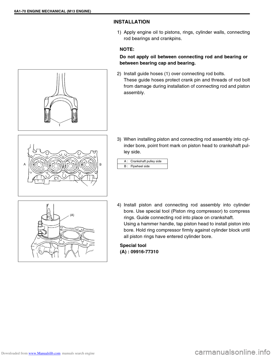
2) Install guide hoses (1) over connecting rod bolts.
These guide hoses protect crank pin and threads of rod bolt
from damage during installation of connecting rod and piston
assembly.
3) When installing piston and connecting rod assembly into cyl-
inder bore, point front mark on piston head to crankshaft pul-
ley side.
4) Install piston and connecting rod assembly into cylinder
bore. Use special tool (Piston ring compressor) to compress
rings. Guide connecting rod into place on crankshaft.
Using a hammer handle, tap piston head to install piston into
bore. Hold ring compressor firmly against cylinder block until
all piston rings have entered cylinder bore.
Special tool
(A) : 09916-77310 NOTE:
Do not apply oil between connecting rod and bearing or
between bearing cap and bearing.
A : Crankshaft pulley side
B : Flywheel side
Page 556 of 687

Downloaded from www.Manualslib.com manuals search engine ENGINE MECHANICAL (M13 ENGINE) 6A1-75
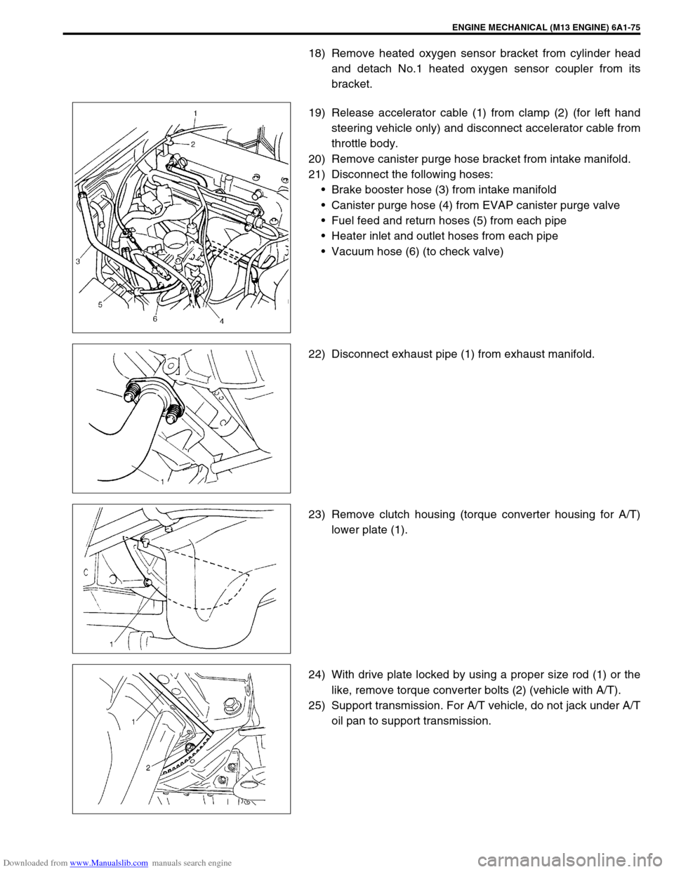
18) Remove heated oxygen sensor bracket from cylinder head
and detach No.1 heated oxygen sensor coupler from its
bracket.
19) Release accelerator cable (1) from clamp (2) (for left hand
steering vehicle only) and disconnect accelerator cable from
throttle body.
20) Remove canister purge hose bracket from intake manifold.
21) Disconnect the following hoses:
Brake booster hose (3) from intake manifold
Canister purge hose (4) from EVAP canister purge valve
Fuel feed and return hoses (5) from each pipe
Heater inlet and outlet hoses from each pipe
Vacuum hose (6) (to check valve)
22) Disconnect exhaust pipe (1) from exhaust manifold.
23) Remove clutch housing (torque converter housing for A/T)
lower plate (1).
24) With drive plate locked by using a proper size rod (1) or the
like, remove torque converter bolts (2) (vehicle with A/T).
25) Support transmission. For A/T vehicle, do not jack under A/T
oil pan to support transmission.
Page 561 of 687
Downloaded from www.Manualslib.com manuals search engine 6A1-80 ENGINE MECHANICAL (M13 ENGINE)
REMOVAL
1) Remove engine assembly from vehicle as previously out-
lined.
2) Remove clutch cover, clutch disc and flywheel (drive plate
for A/T) by using special tool.
Special tool
(A) : 09924-17810
3) Remove the following parts from engine as previously out-
lined.
Oil pan and oil pump strainer
Intake manifold and exhaust manifold
Cylinder head cover
Timing chain cover
Timing chain guide, chain tensioner adjuster, chain ten-
sioner, timing chain and crankshaft timing sprocket
Camshaft, tappet and shim
Cylinder head assembly
Piston and connecting rod
4) Remove rear oil seal housing (1).
5) Loosen bearing cap No.1 and No.2 bolts in such order as
indicated in figure and remove them.
6) Remove crankshaft from cylinder block.
Page 573 of 687

Downloaded from www.Manualslib.com manuals search engine 6A1-92 ENGINE MECHANICAL (M13 ENGINE)
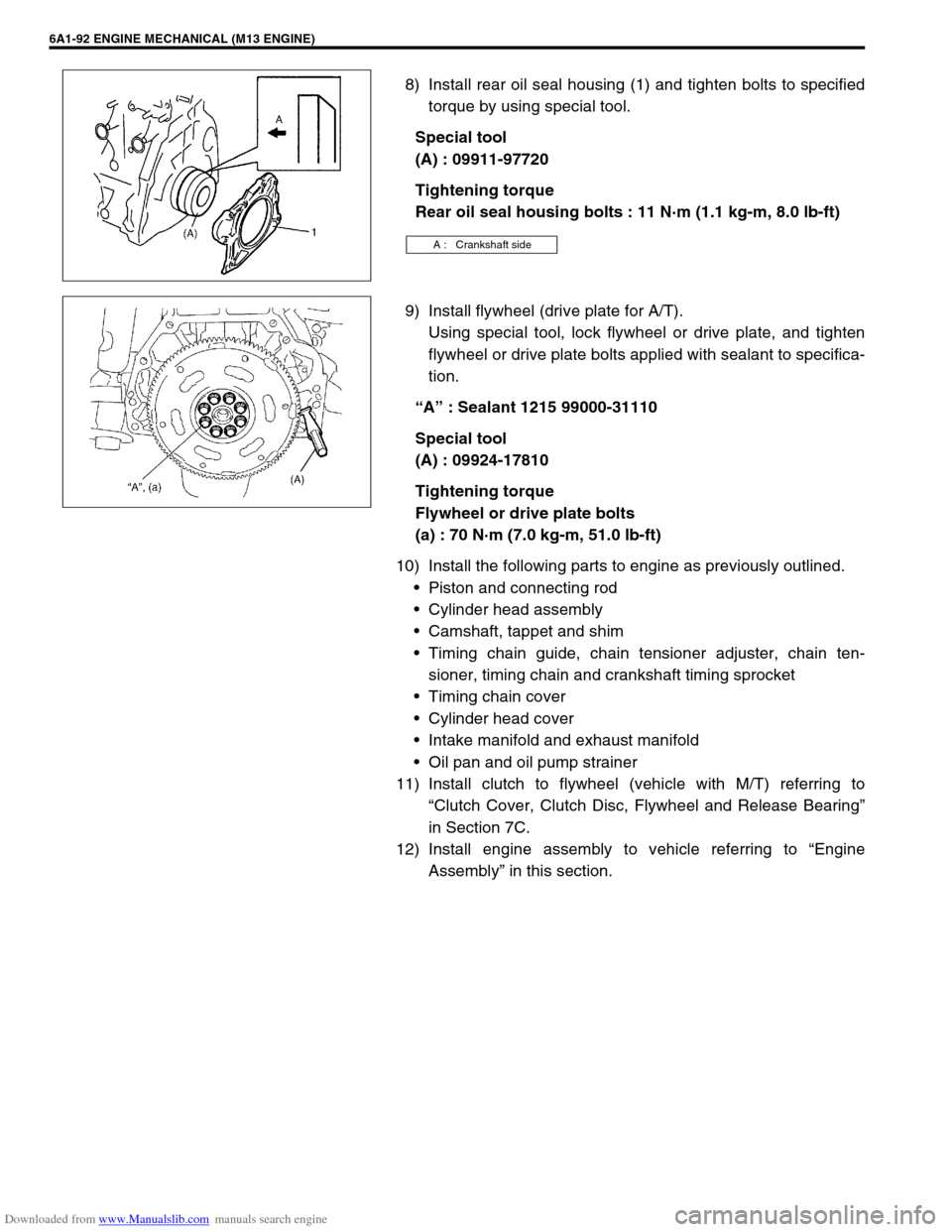
8) Install rear oil seal housing (1) and tighten bolts to specified
torque by using special tool.
Special tool
(A) : 09911-97720
Tightening torque
Rear oil seal housing bolts : 11 N·m (1.1 kg-m, 8.0 lb-ft)
9) Install flywheel (drive plate for A/T).
Using special tool, lock flywheel or drive plate, and tighten
flywheel or drive plate bolts applied with sealant to specifica-
tion.
“A” : Sealant 1215 99000-31110
Special tool
(A) : 09924-17810
Tightening torque
Flywheel or drive plate bolts
(a) : 70 N·m (7.0 kg-m, 51.0 lb-ft)
10) Install the following parts to engine as previously outlined.
Piston and connecting rod
Cylinder head assembly
Camshaft, tappet and shim
Timing chain guide, chain tensioner adjuster, chain ten-
sioner, timing chain and crankshaft timing sprocket
Timing chain cover
Cylinder head cover
Intake manifold and exhaust manifold
Oil pan and oil pump strainer
11) Install clutch to flywheel (vehicle with M/T) referring to
“Clutch Cover, Clutch Disc, Flywheel and Release Bearing”
in Section 7C.
12) Install engine assembly to vehicle referring to “Engine
Assembly” in this section.
A : Crankshaft side
Page 574 of 687

Downloaded from www.Manualslib.com manuals search engine ENGINE MECHANICAL (M13 ENGINE) 6A1-93
Required Service Material
Tightening Torque Specification
MaterialRecommended SUZUKI product
(Part Number)Use
Sealant SUZUKI BOND NO. 1207C
(99000-31150)To apply to mating surface of cylinder block and oil
pan.
To apply to mating surface of cylinder block and
timing chain cover.
To apply to sealing surface of cylinder head cover.
To apply to mating surface to rear oil seal housing.
SUZUKI BOND NO. 1207B
(99000-31140)To apply to mating surface of cylinder block, cylin-
der head and timing chain cover.
SUZUKI BOND NO. 1215
(99000-31110)To flywheel (M/T) or drive plate (A/T) bolts.
Fastening partTightening torque
Nm kg-m lb-ft
Oil pressure switch 14.0 1.4 10.5
Camshaft housing bolts
(for replacement of shim)8.0 0.8 6.0
Camshaft housing bolts 11.0 1.1 8.0
Cylinder head cover bolts 8.0 0.8 6.0
Intake manifold bolts and nuts 25.0 2.5 18.0
Exhaust manifold bolts and nuts 55.0 5.5 40.0
Exhaust pipe bolts 50.0 5.0 36.5
Exhaust manifold stiffener bolts 50.0 5.0 36.5
Oil pump strainer bolt 11.0 1.1 8.0
Oil pump strainer bracket bolt 11.0 1.1 8.0
Oil pan bolts and nuts 11.0 1.1 8.0
Oil pan drain plug 50.0 5.0 36.5
Timing chain cover bolts and nut 23.0 2.3 17.0
Crankshaft pulley bolt 150.0 15.0 108.5
Oil pump rotor plate bolts 11.0 1.1 8.0
Timing chain No.1 guide bolts 9.0 0.9 6.5
Timing chain tensioner adjuster bolts 11.0 1.1 8.0
Venturi plug 5.0 0.5 3.5
Cylinder head bolt for M8 22.0 2.2 16.0
Cylinder head bolts for M10 a) Tighten 40 N·m
b) Turn 60°
c) Turn 60°a) Tighten 4.0 kg-m
b) Turn 60°
c) Turn 60°a) Tighten 29.0 lb-ft
b) Turn 60°
c) Turn 60°
Connecting rod bearing cap nuts a) Tighten 15 N·m
b) Turn 45°
c) Turn 45°a) Tighten 1.5 kg-m
b) Turn 45°
c) Turn 45°a) Tighten 11.0 lb-ft
b) Turn 45°
c) Turn 45°
Engine mounting bolts 50.0 5.0 36.5
Page 579 of 687
Downloaded from www.Manualslib.com manuals search engine 6B-2 ENGINE COOLING
General Description
The cooling system consists of the radiator cap, radiator, reservoir, hoses, water pump, cooling fan & clutch,
thermostat. The radiator is of tube-and-fin type.
Cooling System Circulation
1. Radiator inlet hose 5. Water pump 9. Heater outlet hose
2. Radiator outlet hose 6. Fast idle control plunger of throttle body 10. Radiator
3. Water inlet pipe 7. Cylinder block/cylinder head
4. Thermostat 8. Heater inlet hose
Page 611 of 687

Downloaded from www.Manualslib.com manuals search engine 6E-6 ENGINE AND EMISSION CONTROL SYSTEM
Fuel Delivery System
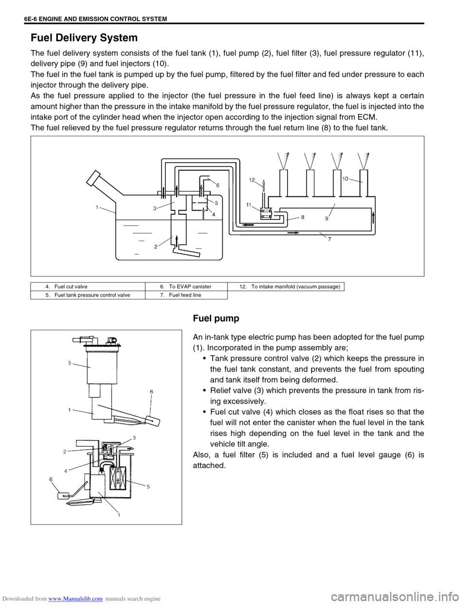
The fuel delivery system consists of the fuel tank (1), fuel pump (2), fuel filter (3), fuel pressure regulator (11),
delivery pipe (9) and fuel injectors (10).
The fuel in the fuel tank is pumped up by the fuel pump, filtered by the fuel filter and fed under pressure to each
injector through the delivery pipe.
As the fuel pressure applied to the injector (the fuel pressure in the fuel feed line) is always kept a certain
amount higher than the pressure in the intake manifold by the fuel pressure regulator, the fuel is injected into the
intake port of the cylinder head when the injector open according to the injection signal from ECM.
The fuel relieved by the fuel pressure regulator returns through the fuel return line (8) to the fuel tank.
Fuel pump
An in-tank type electric pump has been adopted for the fuel pump
(1). Incorporated in the pump assembly are;
Tank pressure control valve (2) which keeps the pressure in
the fuel tank constant, and prevents the fuel from spouting
and tank itself from being deformed.
Relief valve (3) which prevents the pressure in tank from ris-
ing excessively.
Fuel cut valve (4) which closes as the float rises so that the
fuel will not enter the canister when the fuel level in the tank
rises high depending on the fuel level in the tank and the
vehicle tilt angle.
Also, a fuel filter (5) is included and a fuel level gauge (6) is
attached.
4. Fuel cut valve 6. To EVAP canister 12. To intake manifold (vacuum passage)
5. Fuel tank pressure control valve 7. Fuel feed line