2005 SUZUKI JIMNY electric
[x] Cancel search: electricPage 611 of 687
Downloaded from www.Manualslib.com manuals search engine 6E-6 ENGINE AND EMISSION CONTROL SYSTEM
Fuel Delivery System
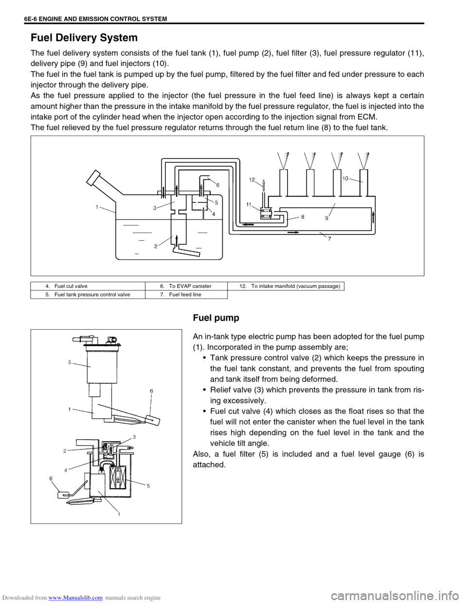
The fuel delivery system consists of the fuel tank (1), fuel pump (2), fuel filter (3), fuel pressure regulator (11),
delivery pipe (9) and fuel injectors (10).
The fuel in the fuel tank is pumped up by the fuel pump, filtered by the fuel filter and fed under pressure to each
injector through the delivery pipe.
As the fuel pressure applied to the injector (the fuel pressure in the fuel feed line) is always kept a certain
amount higher than the pressure in the intake manifold by the fuel pressure regulator, the fuel is injected into the
intake port of the cylinder head when the injector open according to the injection signal from ECM.
The fuel relieved by the fuel pressure regulator returns through the fuel return line (8) to the fuel tank.
Fuel pump
An in-tank type electric pump has been adopted for the fuel pump
(1). Incorporated in the pump assembly are;
Tank pressure control valve (2) which keeps the pressure in
the fuel tank constant, and prevents the fuel from spouting
and tank itself from being deformed.
Relief valve (3) which prevents the pressure in tank from ris-
ing excessively.
Fuel cut valve (4) which closes as the float rises so that the
fuel will not enter the canister when the fuel level in the tank
rises high depending on the fuel level in the tank and the
vehicle tilt angle.
Also, a fuel filter (5) is included and a fuel level gauge (6) is
attached.
4. Fuel cut valve 6. To EVAP canister 12. To intake manifold (vacuum passage)
5. Fuel tank pressure control valve 7. Fuel feed line
Page 613 of 687

Downloaded from www.Manualslib.com manuals search engine 6E-8 ENGINE AND EMISSION CONTROL SYSTEM
Engine & emission control input / output table
INPUTOUTPUT
ELECTRIC CONTROL DEVICE
DIAGNOSIS SWITCH TERMINAL
(VEHICLE WITHOUT IMMOBILIZER INDICATOR LAMP)
BAROMETRIC PRESSURE SENSOR
(VEHICLE WITH IMMOBILIZER INDICATOR LAMP)
STOP LAMP SWITCH
STARTER SWITCH
IGNITION SWITCH
LIGHTING SWITCH
REAR DEFOGGER SWITCH (IF EQUIPPED)
BLOWER SWITCH
A/C SWITCH (IF EQUIPPED)
A/C EVAPORATOR TEMP. SENSOR (IF EQUIPPED)
VSS
HEATED OXYGEN SENSOR-1 (IF EQUIPPED)
HEATED OXYGEN SENSOR-2
(IF EQUIPPED)For detecting deterioration of
three way catalytic converter
IAT SENSOR
ECT SENSOR
TP SENSOR
MAP SENSOR
CMP SENSOR
CKP SENSOR
TEST SWITCH TERMINAL
(VEHICLE WITHOUT IMMOBILIZER INDICATOR LAMP)
KNOCK SENSOR
FUEL PUMP RELAY
FUEL INJECTOR
HO2S HEATER
IAC VALVE
IGNITION COIL WITH IGNITER
EGR VALVE (IF EQUIPPED)
EVAP CANISTER PURGE VALVE
A/C COMPRESSOR CLUTCH
MIL
MAIN RELAY
TRANSMISSION CONTROL MODULE SIGNAL FROM SENSOR, SWITCH AND CONTROL MODULEA/C CONDENSER FAN RELAY
Page 624 of 687
Downloaded from www.Manualslib.com manuals search engine ENGINE AND EMISSION CONTROL SYSTEM 6E-19
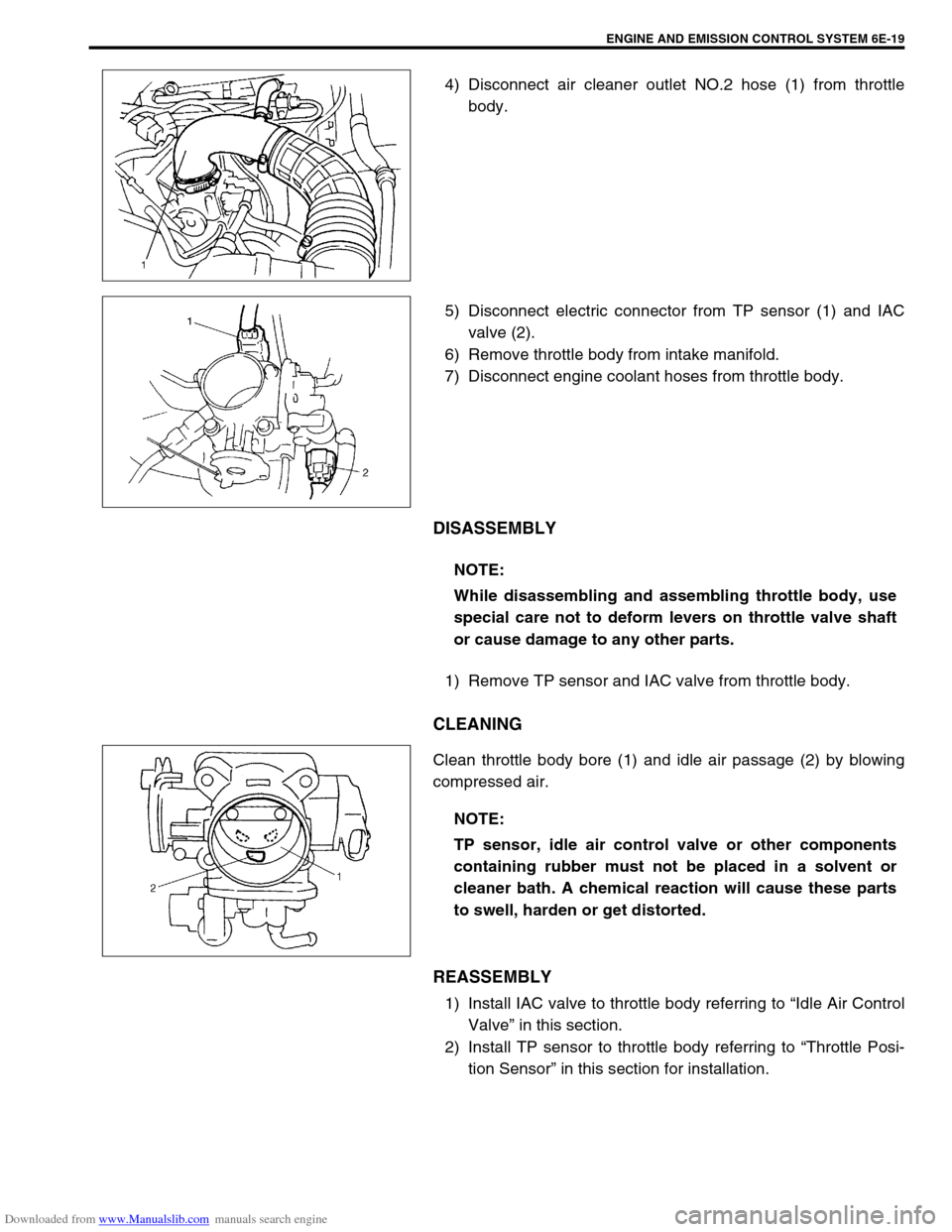
4) Disconnect air cleaner outlet NO.2 hose (1) from throttle
body.
5) Disconnect electric connector from TP sensor (1) and IAC
valve (2).
6) Remove throttle body from intake manifold.
7) Disconnect engine coolant hoses from throttle body.
DISASSEMBLY
1) Remove TP sensor and IAC valve from throttle body.
CLEANING
Clean throttle body bore (1) and idle air passage (2) by blowing
compressed air.
REASSEMBLY
1) Install IAC valve to throttle body referring to “Idle Air Control
Valve” in this section.
2) Install TP sensor to throttle body referring to “Throttle Posi-
tion Sensor” in this section for installation.
NOTE:
While disassembling and assembling throttle body, use
special care not to deform levers on throttle valve shaft
or cause damage to any other parts.
NOTE:
TP sensor, idle air control valve or other components
containing rubber must not be placed in a solvent or
cleaner bath. A chemical reaction will cause these parts
to swell, harden or get distorted.
Page 642 of 687
Downloaded from www.Manualslib.com manuals search engine ENGINE AND EMISSION CONTROL SYSTEM 6E-37
Fuel cut operation
INSPECTION
1) Warm up engine to normal operating temperature.
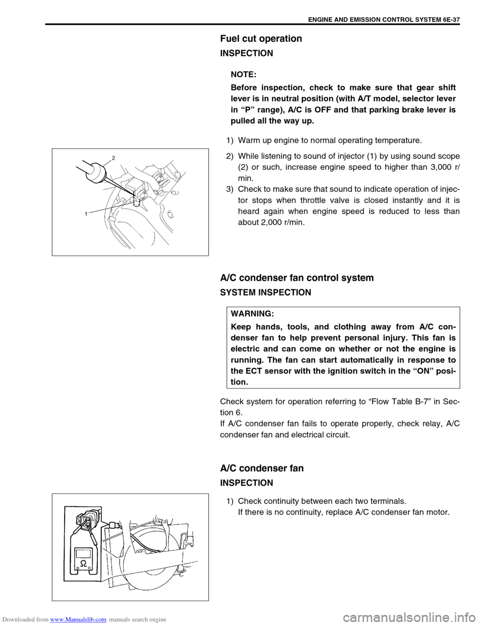
2) While listening to sound of injector (1) by using sound scope
(2) or such, increase engine speed to higher than 3,000 r/
min.
3) Check to make sure that sound to indicate operation of injec-
tor stops when throttle valve is closed instantly and it is
heard again when engine speed is reduced to less than
about 2,000 r/min.
A/C condenser fan control system
SYSTEM INSPECTION
Check system for operation referring to “Flow Table B-7” in Sec-
tion 6.
If A/C condenser fan fails to operate properly, check relay, A/C
condenser fan and electrical circuit.
A/C condenser fan
INSPECTION
1) Check continuity between each two terminals.
If there is no continuity, replace A/C condenser fan motor. NOTE:
Before inspection, check to make sure that gear shift
lever is in neutral position (with A/T model, selector lever
in “P” range), A/C is OFF and that parking brake lever is
pulled all the way up.
WARNING:
Keep hands, tools, and clothing away from A/C con-
denser fan to help prevent personal injury. This fan is
electric and can come on whether or not the engine is
running. The fan can start automatically in response to
the ECT sensor with the ignition switch in the “ON” posi-
tion.
Page 651 of 687
Downloaded from www.Manualslib.com manuals search engine 6F-2 IGNITION SYSTEM (ELECTRONIC IGNITION SYSTEM)
General Description
The ignition system is an electronic (distributorless) ignition system. It consists of the parts as described below
and has an electronic ignition control system.
ECM
It detects the engine and vehicle conditions through the signals from the sensors, determines the most suit-
able ignition timing and time for electricity to flow to the primary coil and sends a signal to the ignitor (power
unit) in the ignition coil assembly.
Ignition coil assembly (including an ignitor)
The ignition coil assembly has a built-in ignitor which turns ON and OFF the current flow to the primary coil
according to the signal from ECM. When the current flow to the primary coil is turned OFF, a high voltage is
induced in the secondary coil.
High tension cords and spark plugs.
CMP sensor (Camshaft position sensor) and CKP sensor (Crankshaft position sensor)
Using signals from these sensors, ECM identifies the specific cylinder whose piston is in the compression
stroke, detects the crank angle and adjust initial ignition timing automatically.
TP sensor, ECT sensor, MAP sensor and other sensors/switches
Refer to “Electronic Control System” in Section 6E for details.
Although this ignition system does not have a distributor, it has two ignition coil assemblies (one is for No.1 and
No.4 spark plugs and the other is for No.2 and No.3 spark plugs). When an ignition signal is sent from ECM to
the ignitor in the ignition coil assembly for No.1 and No.4 spark plugs, a high voltage is induced in the secondary
coil and that passes through the high-tension cords and causes No.1 and No.4 spark plugs to spark simulta-
neously. Likewise, when an ignition signal is sent to the ignitor in the other ignition coil assembly, No.2 and No.3
spark plugs spark simultaneously.
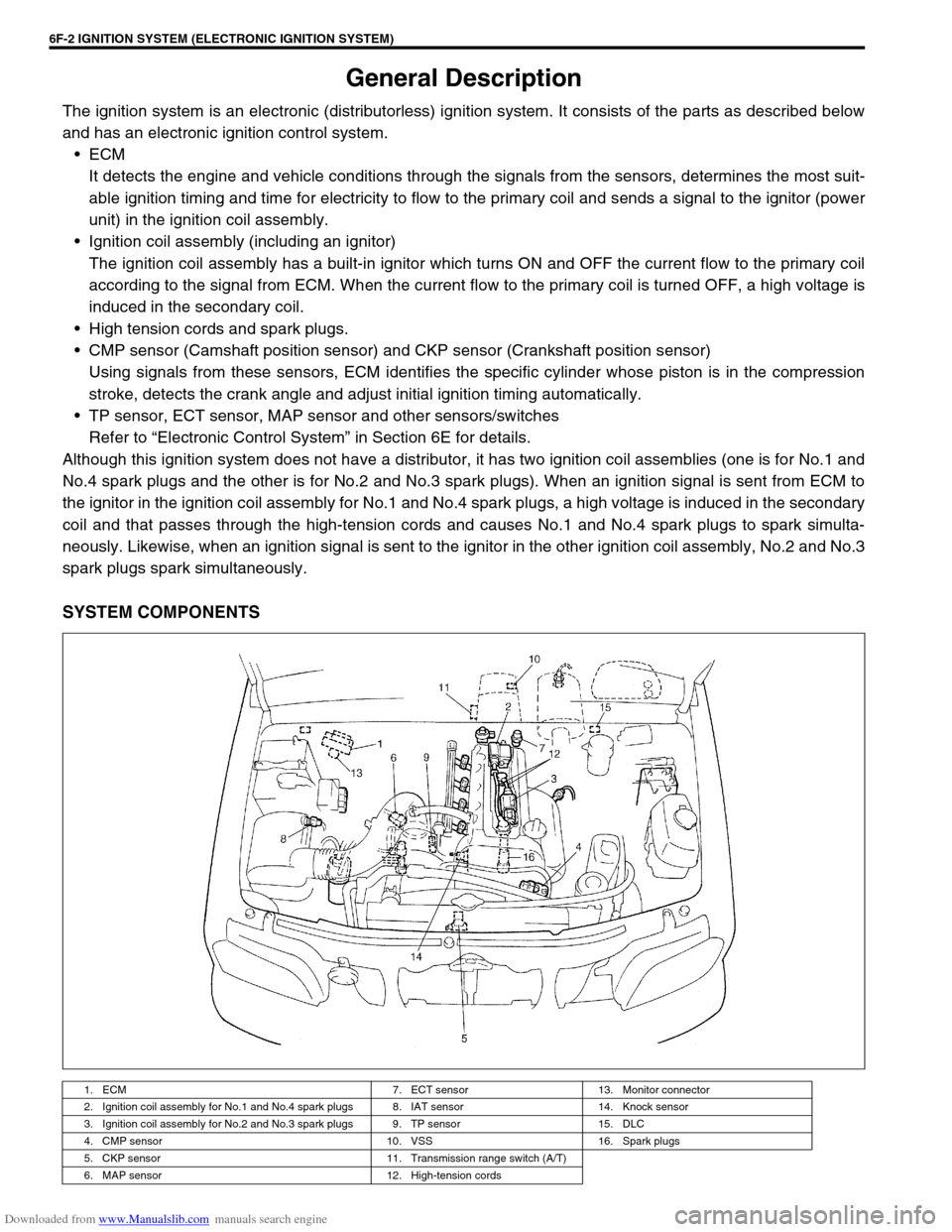
SYSTEM COMPONENTS
1. ECM 7. ECT sensor 13. Monitor connector
2. Ignition coil assembly for No.1 and No.4 spark plugs 8. IAT sensor 14. Knock sensor
3. Ignition coil assembly for No.2 and No.3 spark plugs 9. TP sensor 15. DLC
4. CMP sensor 10. VSS 16. Spark plugs
5. CKP sensor 11. Transmission range switch (A/T)
6. MAP sensor 12. High-tension cords
Page 652 of 687

Downloaded from www.Manualslib.com manuals search engine IGNITION SYSTEM (ELECTRONIC IGNITION SYSTEM 6F-3
SYSTEM WIRING DIAGRAM
Diagnosis
1. Ignition switch 7. No.1 spark plug
2. Main relay 8. No.2 spark plug
3. Ignition coil assembly for No.1 and No.4 spark plugs 9. No.3 spark plug
4. Ignition coil assembly for No.2 and No.3 spark plugs 10. No.4 spark plug
5. CMP sensor 11. Sensed information (MAP sensor, ECT sensor, IAT sensor, TP sensor, Knock sensor, VSS, Park/
Neutral position signal, Electric load signal, Engine start signal, Test switch terminal)
6. CKP sensor
Condition Possible Cause Correction
Engine cranks, but will
not start or hard to
start (No spark)Blown fuse for ignition coil Replace.
Loose connection or disconnection of lead wire
or high-tension cord(s)Connect securely.
Faulty high-tension cord(s) Replace.
Faulty spark plug(s) Adjust, clean or replace.
Faulty ignition coil Replace ignition coil assembly.
Faulty CKP sensor or CKP sensor plate Clean, tighten or replace.
Faulty ECM Replace.
Poor fuel economy or
engine performanceIncorrect ignition timing Check related sensors and CKP
sensor plate.
Faulty spark plug(s) or high-tension cord(s) Adjust, clean or replace.
Faulty ignition coil assembly Replace.
Faulty CKP sensor or CKP sensor plate Clean, tighten or replace.
Faulty ECM Replace.
Page 653 of 687

Downloaded from www.Manualslib.com manuals search engine 6F-4 IGNITION SYSTEM (ELECTRONIC IGNITION SYSTEM)
IGNITION SYSTEM DIAGNOSTIC FLOW TABLE
Step Action Yes No
1Was “Engine Diagnostic Flow Table” in Section 6 per-
formed?Go to Step 2. Go to “Engine Diag.
Flow Table” in Section
6.
2Ignition Spark Test
1) Check all spark plugs for condition and type refer-
ring to “Spark Plugs” section.
2) If OK, perform ignition spark test, referring to “Igni-
tion Spark Test” section.
Is spark emitted from all spark plugs?Go to Step 11. Go to Step 3.
3Diagnostic Trouble Code (DTC) Check
Is DTC stored in ECM?Go to applicable DTC
Diag. Flow Table in
Section 6.Go to Step 4.
4Electrical Connection Check
1) Check ignition coil assemblies and high-tension
cords for electrical connection.
Are they connected securely?Go to Step 5. Connect securely.
5High-tension Cords Check
1) Check high-tension cord for resistance referring to
“High-Tension Cords” section.
Is check result satisfactory?Go to Step 6. Replace high-tension
cord(s).
6Ignition Coil Assembly Power Supply and Ground Cir-
cuit Check
1) Check ignition coil assembly power supply and
ground circuits for open and short.
Are circuits in good condition?Go to Step 7. Repair or replace.
7Ignition Coil Assembly Check
1) Check ignition coil for resistance referring to “Igni-
tion Coil Assembly” section.
Is check result satisfactory?Go to Step 8. Replace ignition coil
assembly.
8Crankshaft Position (CKP) Sensor Check
1) Check crankshaft position sensor referring to Step
2 and 6 of “DTC P0335 (No.23) CKP Sensor Cir-
cuit Malfunction” in Section 6.
Is check result satisfactory?Go to Step 9. Tighten CKP sensor
bolt, replace CKP sen-
sor or CKP sensor
plate.
9Ignition Trigger Signal Circuit Check
1) Check ignition trigger signal wire for open, short
and poor connection.
Is circuit in good condition?Go to Step 10. Repair or replace.
10A Known-good Ignition Coil Assembly Substitution
1) Substitute a known-good ignition coil assembly
and then repeat Step 2.
Is check result of Step 2 satisfactory?Go to Step 11. Substitute a known-
good ECM and then
repeat Step 2.
11Ignition Timing Check
1) Check initial ignition timing and ignition timing
advance referring to “Ignition Timing” section.
Is check result satisfactory?System is in good con-
dition.Check CKP sensor,
CKP sensor plate and
input signals related to
this system.
Page 657 of 687
Downloaded from www.Manualslib.com manuals search engine 6F-8 IGNITION SYSTEM (ELECTRONIC IGNITION SYSTEM)
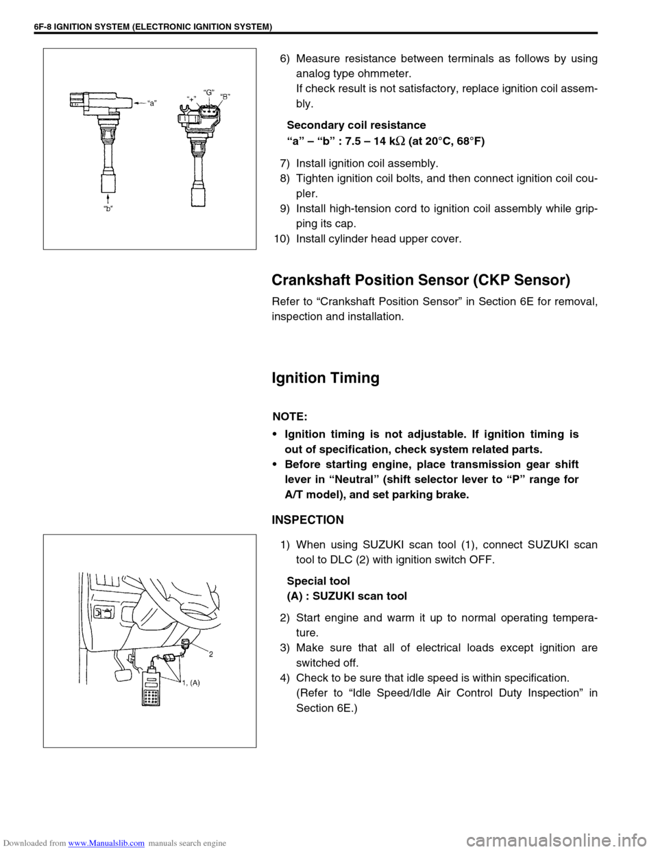
6) Measure resistance between terminals as follows by using
analog type ohmmeter.
If check result is not satisfactory, replace ignition coil assem-
bly.
Secondary coil resistance
“a” – “b” : 7.5 – 14 k
Ω (at 20°C, 68°F)
7) Install ignition coil assembly.
8) Tighten ignition coil bolts, and then connect ignition coil cou-
pler.
9) Install high-tension cord to ignition coil assembly while grip-
ping its cap.
10) Install cylinder head upper cover.
Crankshaft Position Sensor (CKP Sensor)
Refer to “Crankshaft Position Sensor” in Section 6E for removal,
inspection and installation.
Ignition Timing
INSPECTION
1) When using SUZUKI scan tool (1), connect SUZUKI scan
tool to DLC (2) with ignition switch OFF.
Special tool
(A) : SUZUKI scan tool
2) Start engine and warm it up to normal operating tempera-
ture.
3) Make sure that all of electrical loads except ignition are
switched off.
4) Check to be sure that idle speed is within specification.
(Refer to “Idle Speed/Idle Air Control Duty Inspection” in
Section 6E.)
NOTE:
Ignition timing is not adjustable. If ignition timing is
out of specification, check system related parts.
Before starting engine, place transmission gear shift
lever in “Neutral” (shift selector lever to “P” range for
A/T model), and set parking brake.