Page 241 of 687

Downloaded from www.Manualslib.com manuals search engine 3E-22 REAR SUSPENSION
Tightening Torque Specifications
Required Service Materials
Fastening portionTightening torque
Nm kg-m lb-ft
Shock absorber upper and lower bolt 85 8.5 61.5
Bump stopper 50 5.0 36.5
Lateral rod bolt and nut
90 9.0 65.0
Trailing arm nut (Front and Rear)
Brake back plate nut 23 2.3 17.0
Brake pipe flare nut 16 1.6 11.5
Rear differential carrier bolt 23 2.3 17.0
Rear propeller shaft bolt (Differential case side) 50 5.0 36.5
Rear propeller shaft bolt (Shaft No.3 transfer case side) 33 3.3 24.0
Wheel nut 95 9.5 69.0
Wheel speed sensor bolt and harness clamp bolt 10 1.0 7.5
MaterialRecommended SUZUKI product
(Part Number)Use
Lithium greaseSUZUKI SUPER GREASE A
(99000-25010)Oil seal lip
SealantSUZUKI BOND NO. 1215
(99000-31110)Joint seam of differential carrier and
axle housing
Water tight sealantSEALING COMPOUND 366E
(99000-31090)To apply to mating surfaces of brake
back plate and rear axle.
Gear oilFor gear oil information, refer to “Mainte-
nance Service” in Section 7E of this manual.Differential gear
(Rear axle housing)
Page 242 of 687
Downloaded from www.Manualslib.com manuals search engine REAR SUSPENSION 3E-23
Special Tools
09913-75520 09913-85210 09924-74510 1) 09927-18411
Universal puller
Bearing installer Oil seal installer Bearing installer handle 2) 09921-57810
Bearing remover
09941-66010 09942-15510 09943-35511 or
09943-3551209944-96010
Bearing outer race
remover
Bump stopper wrench Sliding hammer Brake drum remover 09921-26010
Bearing outer race
remover collar
09951-16030 09951-26010
Bush remover Bush remover plate
Page 243 of 687
Downloaded from www.Manualslib.com manuals search engine 3E-24 REAR SUSPENSION
Page 266 of 687

Downloaded from www.Manualslib.com manuals search engine BRAKES 5-5
Diagnosis Table
Condition Possible Cause Correction
Not enough braking
forceBrake oil leakage from brake lines Locate leaking point and repair.
Brake disc or pads stained with oil Clean or replace.
Overheated brakes Determine cause and repair.
Poor contact of shoes on brake drum Repair for proper contact.
Brake shoes linings stained with oil or wet with
waterReplace.
Badly worn brake shoe linings Replace.
Defective wheel cylinders Repair or replace.
Malfunctioning caliper assembly Repair or replace.
Air in system Bleed system.
Maladjusted sensor spring length of LSPV Check or adjust.
Broken sensor spring of LSPV Replace.
Defective collar of LSPV Replace.
Malfunctioning ABS (Antilock brake system), if
equippedCheck system and replace as nec-
essary.
Brake pull (Brakes not
working in unison)Pad or shoe linings are wet with water or
stained with oil in some brakesReplace.
Drum-to-shoe clearance out of adjustment in
some brakes (Malfunctioning auto adjusting
mechanism)Check for inoperative auto adjusting
mechanism.
Drum is out of round in some brakes Replace.
Wheel tires are inflated unequally Inflate equally.
Malfunctioning wheel cylinders Repair or replace.
Disturbed front wheel alignment Adjust as prescribed.
Unmatched tires on same axle Tires with approximately the same
amount of tread should be used on
the same axle.
Restricted brake tubes or hoses Check for soft hoses and damaged
lines.
Replace with new hoses and new
double-walled steel brake tubing.
Malfunctioning caliper assembly Check for stuck or sluggish pistons
and proper lubrication of caliper
slide bush.
Loose suspension parts Caliper should slide.
Check all suspension mountings.
Loose calipers Check and torque bolts to specifica-
tions.
Noise (high pitched
squeak without brake
applied)Front lining worn out Replace brake pads.
Rear brake locked pre-
maturelyMaladjusted sensor spring length of LSPV Check or adjust.
Malfunctioning LSPV assembly Replace assembly.
Brake locked
(For vehicles
equipped with ABS)Malfunctioning ABS, if equipped Check system and replace as nec-
essary.
Page 353 of 687
Downloaded from www.Manualslib.com manuals search engine 5E-36 ANTILOCK BRAKE SYSTEM (ABS)
Rear Wheel Speed Sensor
OUTPUT VOLTAGE INSPECTION
Check in the same procedure as that used of front wheel speed
sensor check.
Output AC voltage at 1 to 1 1/3 rotation per second
: 100 mV or more at 38 – 49 Hz
Reference
When using oscilloscope, peak-to-peak voltage at 1 to
1 1/3 rotation per second
: 280 mV or more at 38 – 49 Hz
REMOVAL
1) Disconnect negative cable from battery.
2) Hoist vehicle.
3) Disconnect rear wheel speed sensor coupler (1).
4) Detach ABS wheel sensor wire harness from suspension
frame.
1. Left rear wheel sensor 3. Sensor ring Tightening torque
2. Trailing arm 4. Clamp bolt
2. Rear wheel sensor
Page 600 of 687

Downloaded from www.Manualslib.com manuals search engine ENGINE FUEL 6C-5
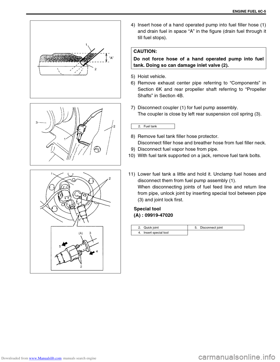
4) Insert hose of a hand operated pump into fuel filler hose (1)
and drain fuel in space “A” in the figure (drain fuel through it
till fuel stops).
5) Hoist vehicle.
6) Remove exhaust center pipe referring to “Components” in
Section 6K and rear propeller shaft referring to “Propeller
Shafts” in Section 4B.
7) Disconnect coupler (1) for fuel pump assembly.
The coupler is close by left rear suspension coil spring (3).
8) Remove fuel tank filler hose protector.
Disconnect filler hose and breather hose from fuel filler neck.
9) Disconnect fuel vapor hose from pipe.
10) With fuel tank supported on a jack, remove fuel tank bolts.
11) Lower fuel tank a little and hold it. Unclamp fuel hoses and
disconnect them from fuel pump assembly (1).
When disconnecting joints of fuel feed line and return line
from pipe, unlock joint by inserting special tool between pipe
(3) and joint lock first.
Special tool
(A) : 09919-47020 CAUTION:
Do not force hose of a hand operated pump into fuel
tank. Doing so can damage inlet valve (2).
2. Fuel tank
2. Quick joint 5. Disconnect joint
4. Insert special tool