Page 116 of 687

Downloaded from www.Manualslib.com manuals search engine STEERING, SUSPENSION, WHEELS AND TIRES 3-7
Radial Tire Lead
“Lead” is the deviation of the vehicle from a straight path on a level rod even with no pressure on the steering
wheel.
Lead is usually caused by:
1) Incorrect alignment.
2) Uneven brake adjustment.
3) Tire construction.
The way in which a tire is built can produce lead in a vehicle. An example of this is placement of the belt. Off
center belts on radial tires can cause the tire to develop a side force while rolling straight down the road. If one
side of the tire has a little larger diameter than the other, the tire will tend to roll to one side. This will develop a
side force which can produce vehicle lead.
The procedure in above figure (Lead Diagnosis) should be used to make sure that front alignment is not mis-
taken for tire lead.
1) Part of the lead diagnosis procedure is different from the proper tire rotation pattern currently in the owner
and service manuals. If a medium to high mileage tire is moved to the other side of the vehicle, be sure to
check that ride roughness has not developed.
2) Rear tires will not cause lead.
Vibration Diagnosis
Wheel unbalance causes most of the highway speed vibration problems. If a vibration remains after dynamic
balancing, its possible causes are as follows.
1) Tire runout.
2) Wheel runout.
3) Tire stiffness variation.
Measuring tire and/or wheel free runout will uncover only part of the problem. All three causes, known as loaded
radial runout, must be checked by using a Tire Problem Detector (TPD). If TPD is not available, alternative
method of substituting known good tire and wheel assemblies on the problem vehicle can be used, although it
takes a longer time.
[A] : Tire out of round 1. Smooth road
[B] : Tire stiffness variation 2. Suspension movement (loaded runout)
[C] : Rim bent or out of round
Page 210 of 687

Downloaded from www.Manualslib.com manuals search engine FRONT SUSPENSION 3D-37
INSTALLATION
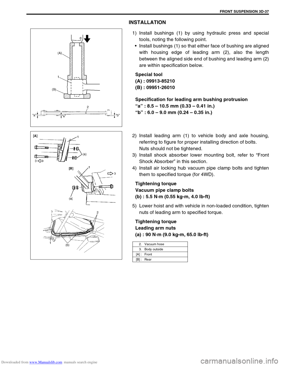
1) Install bushings (1) by using hydraulic press and special
tools, noting the following point.
Install bushings (1) so that either face of bushing are aligned
with housing edge of leading arm (2), also the length
between the aligned side end of bushing and leading arm (2)
are within specification below.
Special tool
(A) : 09913-85210
(B) : 09951-26010
Specification for leading arm bushing protrusion
“a” : 8.5 – 10.5 mm (0.33 – 0.41 in.)
“b” : 6.0 – 9.0 mm (0.24 – 0.35 in.)
2) Install leading arm (1) to vehicle body and axle housing,
referring to figure for proper installing direction of bolts.
Nuts should not be tightened.
3) Install shock absorber lower mounting bolt, refer to “Front
Shock Absorber” in this section.
4) Install air locking hub vacuum pipe clamp bolts and tighten
them to specified torque (for 4WD).
Tightening torque
Vacuum pipe clamp bolts
(b) : 5.5 N·m (0.55 kg-m, 4.0 lb-ft)
5) Lower hoist and with vehicle in non-loaded condition, tighten
nuts of leading arm to specified torque.
Tightening torque
Leading arm nuts
(a) : 90 N·m (9.0 kg-m, 65.0 lb-ft)
2. Vacuum hose
3. Body outside
[A] : Front
[B] : Rear
Page 213 of 687
Downloaded from www.Manualslib.com manuals search engine 3D-40 FRONT SUSPENSION
19) Lower floor jack until tension of suspension coil spring
becomes a little loose and remove right and left sides lower
mounting bolt of shock absorber (1).
20) Remove front mounting bolts of leading arm.
21) Lower front axle housing gradually.
22) Remove axle housing.
INSTALLATION
1) Place rear axle housing on floor jack. Then install leading
arm front mounting bolts (right & left) in proper direction as
shown. At this time, mount nuts but don’t tighten them.
2) Install lower part of shock absorber (1) to right and left sides
of axle housing and install bolts (2) in proper direction as
shown in figure. At this time, mount nuts (3) but don’t tighten
them.
A : Body outside
Page 220 of 687

Downloaded from www.Manualslib.com manuals search engine REAR SUSPENSION 3E-1
6F1
6F2
6G
1A
6K
7A
7A1
7B1
3E
8A
8B
8A
8B
8C
8D
8E
9
10
10A
10B
SECTION 3E
REAR SUSPENSION
CONTENTS
General Description ....................................... 3E-2
Diagnosis ........................................................ 3E-3
Diagnosis Table ........................................... 3E-3
Rear Shock Absorber Check ........................ 3E-3
Trailing Arm, Lateral Rod, Axle Housing
and Coil Spring Check ................................. 3E-3
Trailing Arm and Lateral Rod Bush Check ... 3E-3
Rear Suspension Fasteners ......................... 3E-4
Bearing Retainer and Axle Shaft Oil Seal
Check ........................................................... 3E-4
Bump Stopper and Spring Rubber Seat
Check ........................................................... 3E-4
Wheel Disc, Nut and Bearing Check ............ 3E-4On-Vehicle Service ........................................ 3E-5
Rear Shock Absorber................................... 3E-5
Coil Spring ................................................... 3E-6
Bump Stopper .............................................. 3E-9
Lateral Rod .................................................. 3E-9
Trailing Arm / Bushing................................ 3E-10
Rear Axle Shaft and Wheel Bearing .......... 3E-12
Rear Axle Shaft Inner Oil Seal ................... 3E-17
Rear Axle Housing ..................................... 3E-18
Tightening Torque Specifications .............. 3E-22
Required Service Materials ......................... 3E-22
Special Tools ................................................ 3E-23
WARNING:
When hoisting vehicle, be sure to select the lifting point suitable for the service work referring to Sec-
tion 0A.
NOTE:
All suspension fasteners are an important attaching part in that it could affect the performance of
vital parts and systems, and/or could result in major repair expense. They must be replaced with
one of the same part number or with an equivalent part if replacement becomes necessary. Do not
use a replacement part of lesser quality or substitute design. Torque values must be used as speci-
fied during reassembly to assure proper retention of this part.
Never attempt to heat, quench or straighten any suspension part. Replace it with a new part, or
damage to the part may result.
Page 221 of 687
Downloaded from www.Manualslib.com manuals search engine 3E-2 REAR SUSPENSION
General Description
1. Rear axle housing 4. Bearing oil seal 7. Brake drum 10. Bump stopper
2. Rear wheel bearing 5. Oil seal protector 8. Rear axle shaft 11. Coil spring
3. Bearing retainer ring 6. Lateral rod 9. Shock absorber 12. Trailing arm
Page 222 of 687

Downloaded from www.Manualslib.com manuals search engine REAR SUSPENSION 3E-3
Diagnosis
Diagnosis Table
Refer to “Diagnosis Table” in Section 3.
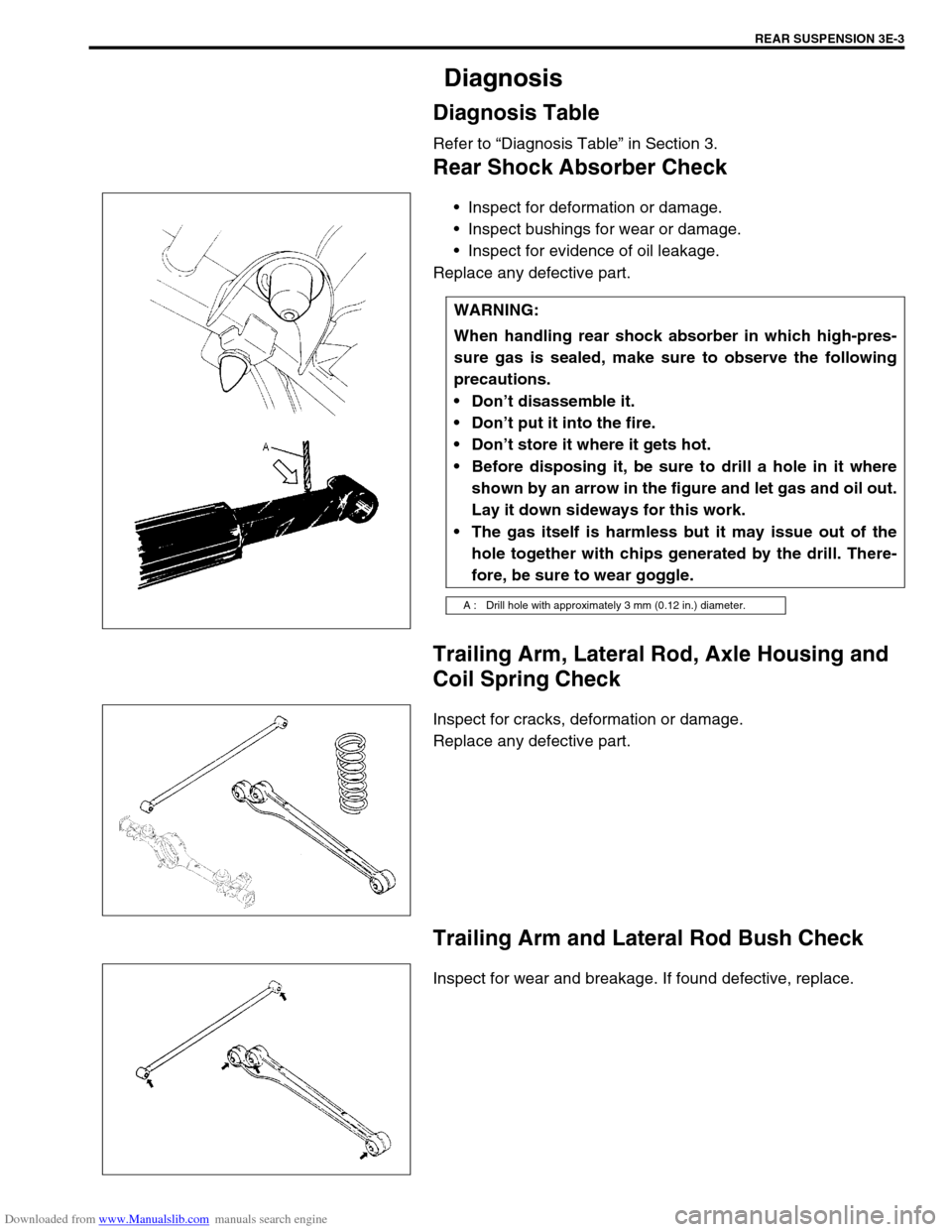
Rear Shock Absorber Check
Inspect for deformation or damage.
Inspect bushings for wear or damage.
Inspect for evidence of oil leakage.
Replace any defective part.
Trailing Arm, Lateral Rod, Axle Housing and
Coil Spring Check
Inspect for cracks, deformation or damage.
Replace any defective part.
Trailing Arm and Lateral Rod Bush Check
Inspect for wear and breakage. If found defective, replace.WARNING:
When handling rear shock absorber in which high-pres-
sure gas is sealed, make sure to observe the following
precautions.
Don’t disassemble it.
Don’t put it into the fire.
Don’t store it where it gets hot.
Before disposing it, be sure to drill a hole in it where
shown by an arrow in the figure and let gas and oil out.
Lay it down sideways for this work.
The gas itself is harmless but it may issue out of the
hole together with chips generated by the drill. There-
fore, be sure to wear goggle.
A : Drill hole with approximately 3 mm (0.12 in.) diameter.
Page 223 of 687

Downloaded from www.Manualslib.com manuals search engine 3E-4 REAR SUSPENSION
Rear Suspension Fasteners
Check each bolt and nut fastening suspension parts for tightness.
Tighten loose one, if any, to specified torque, referring to “Tighten-
ing Torque Specifications” of this section.
Bearing Retainer and Axle Shaft Oil Seal
Check
When brake drum has been removed, check inside of brake
drum for gear oil leakage.
Also, check backside of brake back plate for oil leakage.If oil
leakage is found, replace defective oil seal.
Whenever it is possible to check oil seal during disassembly,
check its lip for wear.
If oil leakage or worn lip is found, replace defective oil seal.
Bump Stopper and Spring Rubber Seat Check
Inspect for wear and breakage. If found defective, replace.
Wheel Disc, Nut and Bearing Check
Inspect each wheel disc for dents, distortion and cracks. A
disc in badly damaged condition must be replaced.
Check wheel hub nuts for tightness and, as necessary,
retighten to specification.
Tightening torque
Wheel nuts
(a) : 95 N·m (9.5 kg-m, 69.0 lb-ft)
Page 224 of 687
Downloaded from www.Manualslib.com manuals search engine REAR SUSPENSION 3E-5
Check wheel bearings for wear. When measuring thrust
play, apply a dial gauge to axle shaft center after removing
wheel center cap from wheel disc.
When measurement exceeds limit, replace bearing.
Rear wheel bearing thrust play limit
: 0.8 mm (0.03 in.)
By rotating wheel actually, check wheel bearing for noise and
smooth rotation. If it is defective, replace bearing.
On-Vehicle Service
Rear Shock Absorber
The shock absorber is non-adjustable, non-refillable, and cannot be disassembled. The only service the shock
absorber requires is replacement when it has lost its resistance, is damaged, or leaking fluid.
REMOVAL
1) Hoist vehicle.
2) Support rear axle housing (1) by using floor jack (2) to pre-
vent it from lowering.
WARNING:
When discarding shock absorber, be sure to refer to instructions in “Rear Shock Absorber Check” in
this section for proper procedure as it is gas sealed type.