Page 580 of 687

Downloaded from www.Manualslib.com manuals search engine ENGINE COOLING 6B-3
Radiator Cap
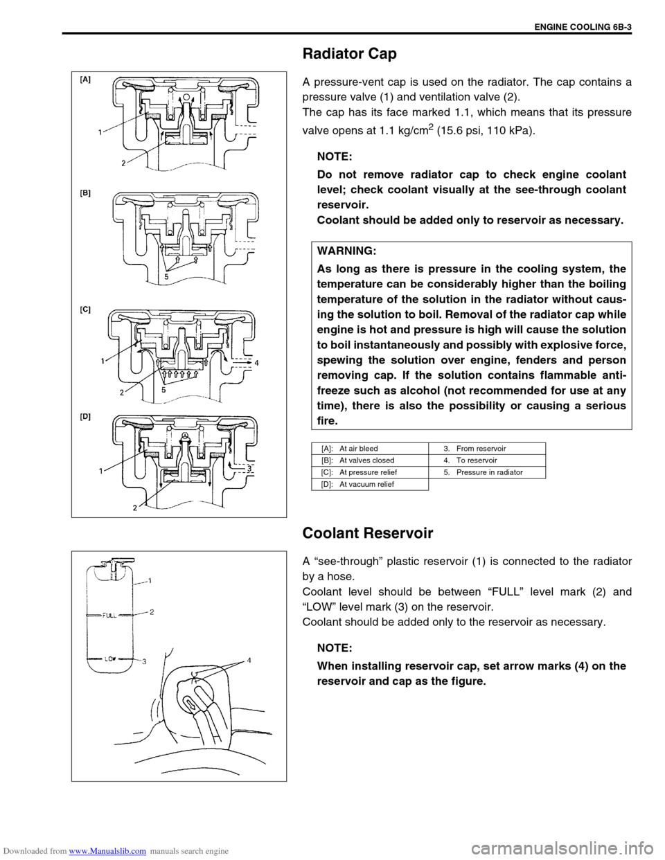
A pressure-vent cap is used on the radiator. The cap contains a
pressure valve (1) and ventilation valve (2).
The cap has its face marked 1.1, which means that its pressure
valve opens at 1.1 kg/cm
2 (15.6 psi, 110 kPa).
Coolant Reservoir
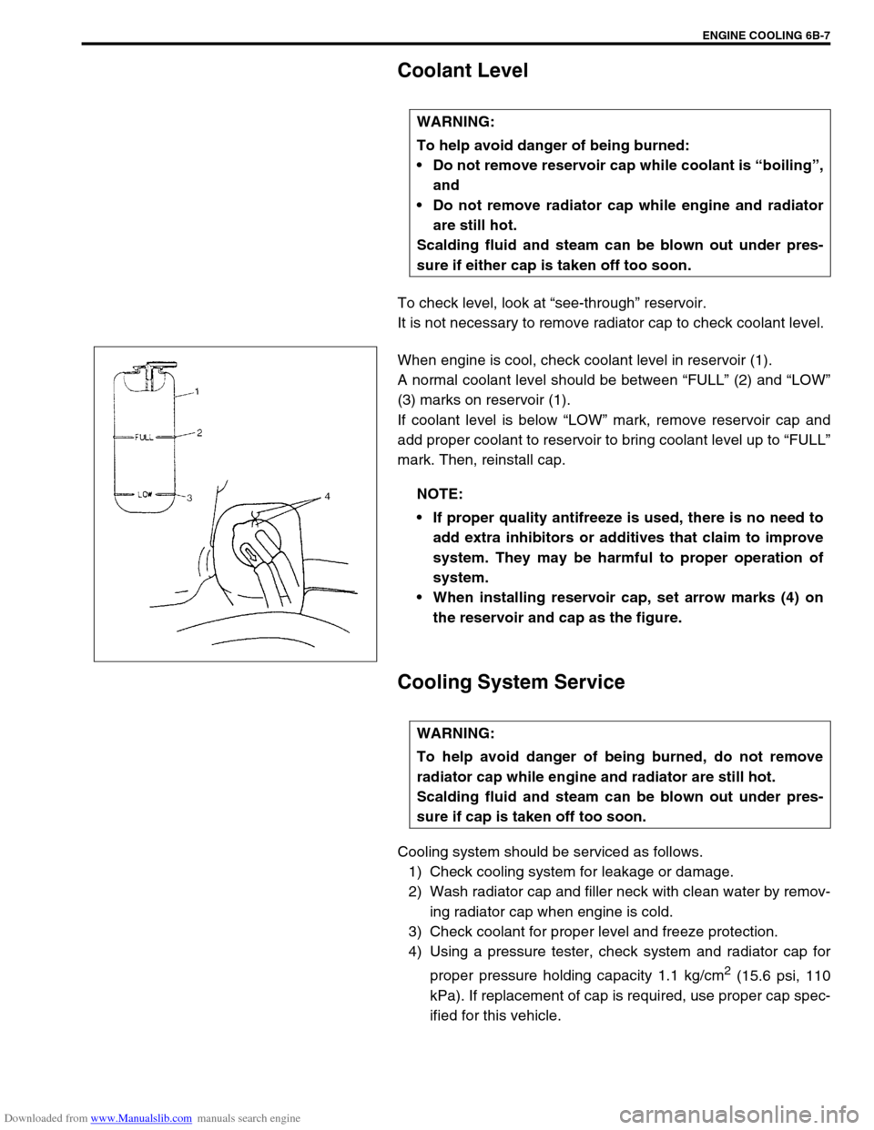
A “see-through” plastic reservoir (1) is connected to the radiator
by a hose.
Coolant level should be between “FULL” level mark (2) and
“LOW” level mark (3) on the reservoir.
Coolant should be added only to the reservoir as necessary.NOTE:
Do not remove radiator cap to check engine coolant
level; check coolant visually at the see-through coolant
reservoir.
Coolant should be added only to reservoir as necessary.
WARNING:
As long as there is pressure in the cooling system, the
temperature can be considerably higher than the boiling
temperature of the solution in the radiator without caus-
ing the solution to boil. Removal of the radiator cap while
engine is hot and pressure is high will cause the solution
to boil instantaneously and possibly with explosive force,
spewing the solution over engine, fenders and person
removing cap. If the solution contains flammable anti-
freeze such as alcohol (not recommended for use at any
time), there is also the possibility or causing a serious
fire.
[A]: At air bleed 3. From reservoir
[B]: At valves closed 4. To reservoir
[C]: At pressure relief 5. Pressure in radiator
[D]: At vacuum relief
NOTE:
When installing reservoir cap, set arrow marks (4) on the
reservoir and cap as the figure.
Page 582 of 687
Downloaded from www.Manualslib.com manuals search engine ENGINE COOLING 6B-5
Diagnosis
Condition Possible Cause Correction
Engine overheats
Loose or broken water pump belt
Not enough coolant
Faulty thermostat
Faulty water pump
Dirty or bent radiator fins
Coolant leakage on cooling system
Defective cooling fan clutch
Plugged radiator
Faulty radiator cap
Maladjusted ignition timing
Dragging brakes
Slipping clutchAdjust or replace.
Check coolant level and add as
necessary.
Replace.
Replace.
Clean or remedy.
Repair.
Check and replace as necessary.
Check and replace radiator as
necessary.
Replace.
Check system related parts.
Adjust brake.
Adjust or replace.
Page 584 of 687

Downloaded from www.Manualslib.com manuals search engine ENGINE COOLING 6B-7
Coolant Level
To check level, look at “see-through” reservoir.
It is not necessary to remove radiator cap to check coolant level.
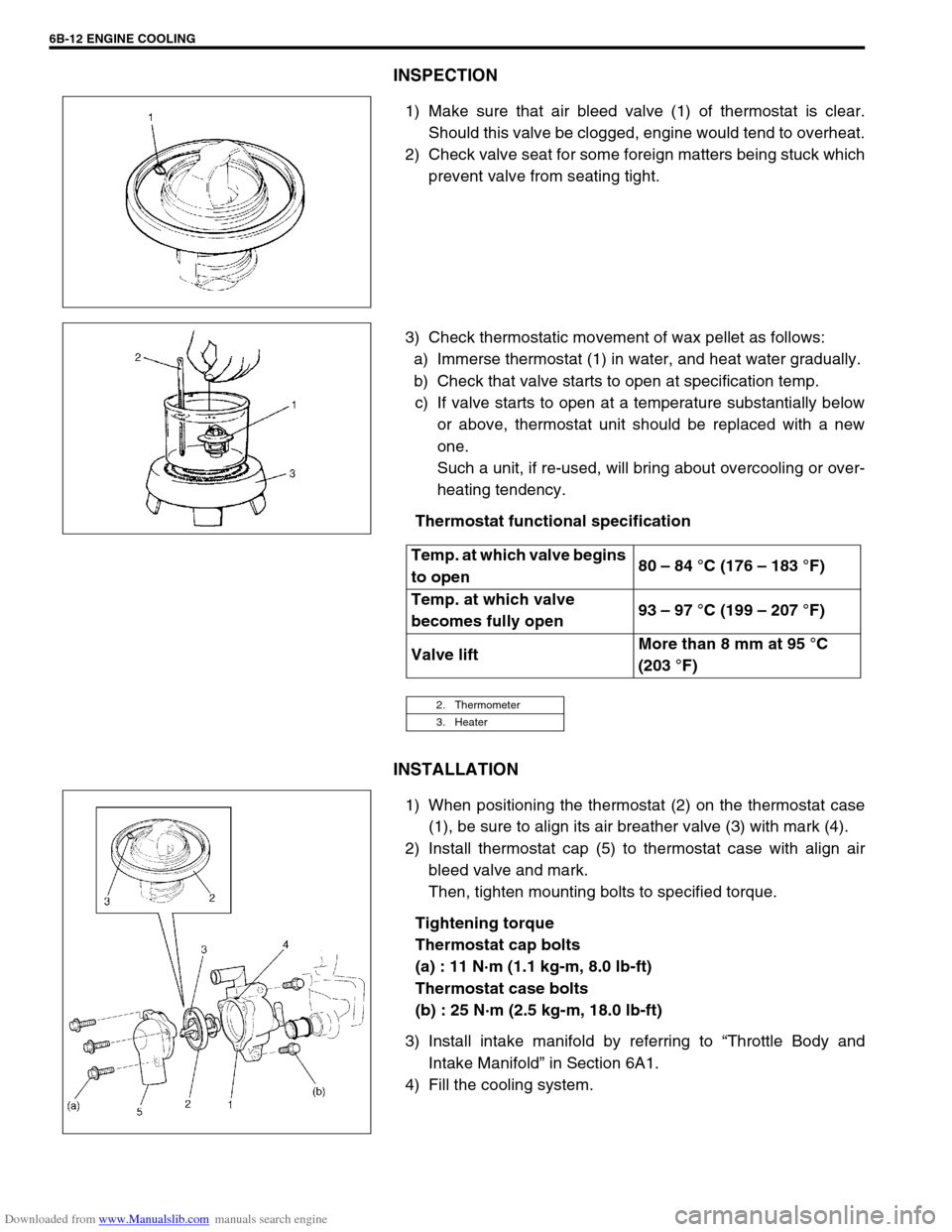
When engine is cool, check coolant level in reservoir (1).
A normal coolant level should be between “FULL” (2) and “LOW”
(3) marks on reservoir (1).
If coolant level is below “LOW” mark, remove reservoir cap and
add proper coolant to reservoir to bring coolant level up to “FULL”
mark. Then, reinstall cap.
Cooling System Service
Cooling system should be serviced as follows.
1) Check cooling system for leakage or damage.
2) Wash radiator cap and filler neck with clean water by remov-
ing radiator cap when engine is cold.
3) Check coolant for proper level and freeze protection.
4) Using a pressure tester, check system and radiator cap for
proper pressure holding capacity 1.1 kg/cm
2 (15.6 psi, 110
kPa). If replacement of cap is required, use proper cap spec-
ified for this vehicle. WARNING:
To help avoid danger of being burned:
Do not remove reservoir cap while coolant is “boiling”,
and
Do not remove radiator cap while engine and radiator
are still hot.
Scalding fluid and steam can be blown out under pres-
sure if either cap is taken off too soon.
NOTE:
If proper quality antifreeze is used, there is no need to
add extra inhibitors or additives that claim to improve
system. They may be harmful to proper operation of
system.
When installing reservoir cap, set arrow marks (4) on
the reservoir and cap as the figure.
WARNING:
To help avoid danger of being burned, do not remove
radiator cap while engine and radiator are still hot.
Scalding fluid and steam can be blown out under pres-
sure if cap is taken off too soon.
Page 586 of 687

Downloaded from www.Manualslib.com manuals search engine ENGINE COOLING 6B-9
9) Run engine, with radiator cap removed, until radiator upper
hose is hot.
10) With engine idling, add coolant to radiator until level reaches
the bottom of filler neck. Install radiator cap, making sure
that the ear of cap lines up with reservoir hose.
Water Pump Belt Tension
1) Inspect belt for cracks, cuts, deformation, wear and cleanli-
ness. If it is necessary to replace belt, refer to “Water Pump
Belt and Cooling Fan” in this section.
2) Check belt for tension. Belt is in proper tension when it
deflects 4.5 to 5.5 mm (0.18 – 0.22 in.) under thumb pres-
sure (about 10 kg or 22 lb.).
Water pump belt tension
“a” : 4.5 – 5.5 mm (0.18 – 0.22 in.) as deflection / 10 kg (22
lbs)
3) If belt is too tight or too loose, adjust it to proper tension by
displacing generator position.
4) Tighten generator adjusting bolt and pivot bolts as specified
torque.
Tightening torque
Generator adjusting bolt (a) : 23 N·m (2.3 kg-m, 17.0 lb-ft)
Generator pivot bolts (b) : 50 N·m (5.0 kg-m, 36.0 lb-ft)
5) Connect negative cable at battery terminal.WARNING:
Disconnect negative cable at battery before checking and
adjusting belt tension.
NOTE:
When replacing belt with a new one, adjust belt tension
to 3 – 4 mm (0.12 – 0.16 in.).
Page 587 of 687
Downloaded from www.Manualslib.com manuals search engine 6B-10 ENGINE COOLING
On-Vehicle Service
Cooling System Component
CAUTION:
Check to make sure that engine coolant temperature is cold before removing any part of cooling
system.
Disconnect negative cable at battery before removing any part.
1. Radiator 6. Thermostat 11. Water outlet cap
2. Reservoir 7. Thermostat cap 12. Thermostat case outlet pipe
3. Cooling fan shroud 8. Radiator outlet pipe 13. Thermostat cap bolt
4. Water outlet pipe 9. Heater pipe 14. Thermostat case bolt
5. Thermostat case 10. ECT sensor Tightening Torque
814 25 N·m (2.5 kg-m) 10 15 N·m (1.5 kg-m)
12 5
6
7
13 11 N·m
(1.1 kg-m) 119421
3
Page 589 of 687

Downloaded from www.Manualslib.com manuals search engine 6B-12 ENGINE COOLING
INSPECTION
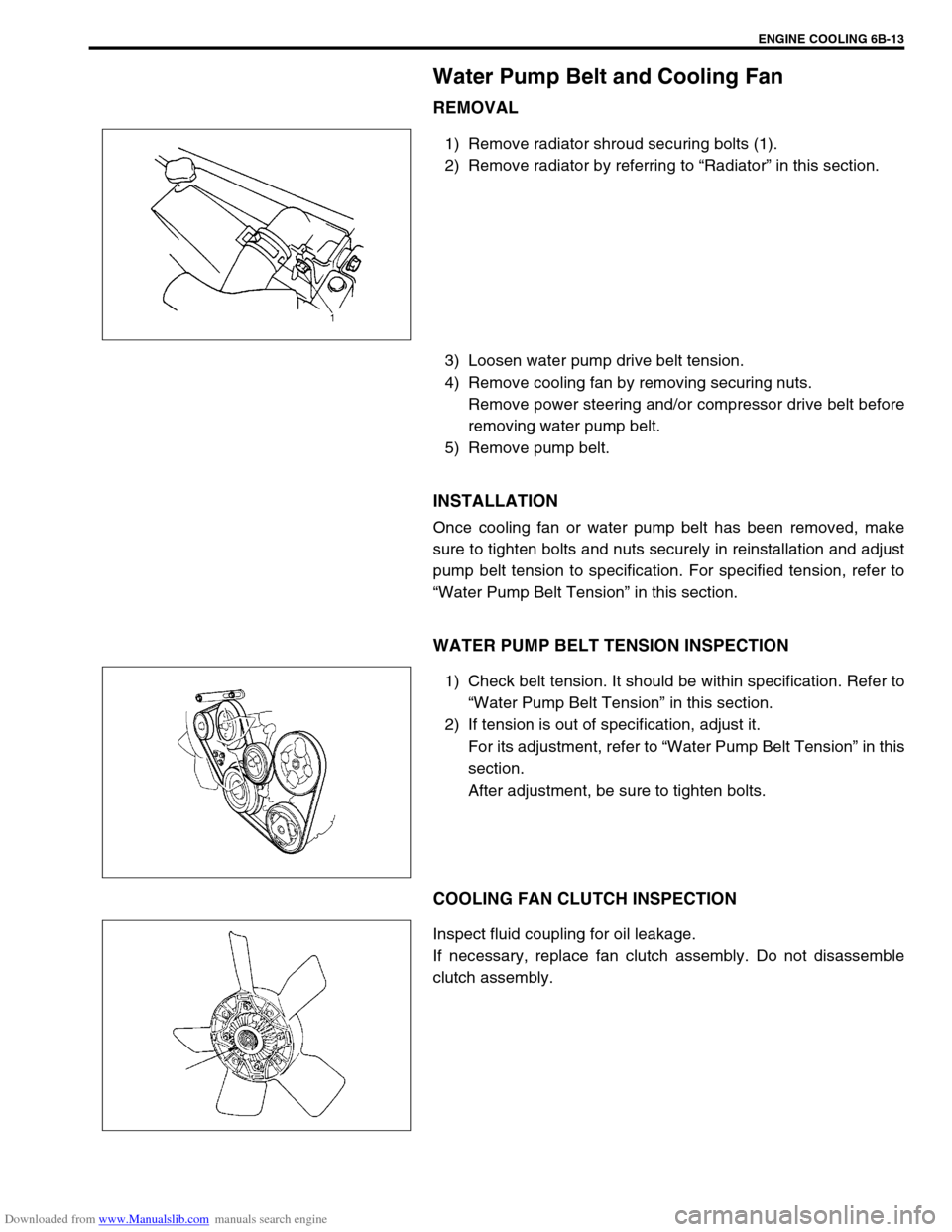
1) Make sure that air bleed valve (1) of thermostat is clear.
Should this valve be clogged, engine would tend to overheat.
2) Check valve seat for some foreign matters being stuck which
prevent valve from seating tight.
3) Check thermostatic movement of wax pellet as follows:
a) Immerse thermostat (1) in water, and heat water gradually.
b) Check that valve starts to open at specification temp.
c) If valve starts to open at a temperature substantially below
or above, thermostat unit should be replaced with a new
one.
Such a unit, if re-used, will bring about overcooling or over-
heating tendency.
Thermostat functional specification
INSTALLATION
1) When positioning the thermostat (2) on the thermostat case
(1), be sure to align its air breather valve (3) with mark (4).
2) Install thermostat cap (5) to thermostat case with align air
bleed valve and mark.
Then, tighten mounting bolts to specified torque.
Tightening torque
Thermostat cap bolts
(a) : 11 N·m (1.1 kg-m, 8.0 lb-ft)
Thermostat case bolts
(b) : 25 N·m (2.5 kg-m, 18.0 lb-ft)
3) Install intake manifold by referring to “Throttle Body and
Intake Manifold” in Section 6A1.
4) Fill the cooling system.
Temp. at which valve begins
to open80 – 84 °C (176 – 183 °F)
Temp. at which valve
becomes fully open93 – 97 °C (199 – 207 °F)
Valve liftMore than 8 mm at 95 °C
(203 °F)
2. Thermometer
3. Heater
Page 590 of 687

Downloaded from www.Manualslib.com manuals search engine ENGINE COOLING 6B-13
Water Pump Belt and Cooling Fan
REMOVAL
1) Remove radiator shroud securing bolts (1).
2) Remove radiator by referring to “Radiator” in this section.
3) Loosen water pump drive belt tension.
4) Remove cooling fan by removing securing nuts.
Remove power steering and/or compressor drive belt before
removing water pump belt.
5) Remove pump belt.
INSTALLATION
Once cooling fan or water pump belt has been removed, make
sure to tighten bolts and nuts securely in reinstallation and adjust
pump belt tension to specification. For specified tension, refer to
“Water Pump Belt Tension” in this section.
WATER PUMP BELT TENSION INSPECTION
1) Check belt tension. It should be within specification. Refer to
“Water Pump Belt Tension” in this section.
2) If tension is out of specification, adjust it.
For its adjustment, refer to “Water Pump Belt Tension” in this
section.
After adjustment, be sure to tighten bolts.
COOLING FAN CLUTCH INSPECTION
Inspect fluid coupling for oil leakage.
If necessary, replace fan clutch assembly. Do not disassemble
clutch assembly.
Page 591 of 687

Downloaded from www.Manualslib.com manuals search engine 6B-14 ENGINE COOLING
Radiator
REMOVAL
1) Drain cooling system.
2) Remove radiator shroud.
3) Disconnect water hoses from radiator.
4) With automatic transmission (A/T) vehicle, disconnect addi-
tional two fluid hoses from radiator.
Place some container under radiator to receive A/T fluid
which will flow out when hose is disconnected.
5) Install radiator protection board to between radiator and
cooling fan.
6) Remove radiator after removing two bolts (1).
INSPECTION
If the water side of the radiator is found excessively rusted or cov-
ered with scales, clean it by flushing with the radiator cleaner
compound.
This flushing should be carried out at regular intervals for scale or
rust formation advances with time even where a recommended
type of coolant is used. Periodical flushing will prove more eco-
nomical.
Inspect the radiator cores and straighten the flattened or bent
fins, if any. Clean the cores, removing road grimes and trashes.
Excessive rust or scale formation on the wet side of the radiator
lowers the cooling efficiency.
Flattened or bent fins obstruct the flow of air through the core to
impede heat dissipation.
Radiator flushing interval recommended
Two years
INSTALLATION
Reverse removal procedures.
NOTE:
Refill cooling system with proper coolant referring to
“Coolant” and “Cooling System Flush and Refill” in
this section.
With automatic transmission vehicle, fill A/T fluid up to
specified level. For procedure to check A/T fluid and its
level, refer to “Changing Fluid” in Section 7B.
After installation, check each joint for leakage.