Page 223 of 687

Downloaded from www.Manualslib.com manuals search engine 3E-4 REAR SUSPENSION
Rear Suspension Fasteners
Check each bolt and nut fastening suspension parts for tightness.
Tighten loose one, if any, to specified torque, referring to “Tighten-
ing Torque Specifications” of this section.
Bearing Retainer and Axle Shaft Oil Seal
Check
When brake drum has been removed, check inside of brake
drum for gear oil leakage.
Also, check backside of brake back plate for oil leakage.If oil
leakage is found, replace defective oil seal.
Whenever it is possible to check oil seal during disassembly,
check its lip for wear.
If oil leakage or worn lip is found, replace defective oil seal.
Bump Stopper and Spring Rubber Seat Check
Inspect for wear and breakage. If found defective, replace.
Wheel Disc, Nut and Bearing Check
Inspect each wheel disc for dents, distortion and cracks. A
disc in badly damaged condition must be replaced.
Check wheel hub nuts for tightness and, as necessary,
retighten to specification.
Tightening torque
Wheel nuts
(a) : 95 N·m (9.5 kg-m, 69.0 lb-ft)
Page 225 of 687
Downloaded from www.Manualslib.com manuals search engine 3E-6 REAR SUSPENSION
3) Remove upper mounting bolt (2).
4) Remove lower mounting bolt (3).
5) Remove shock absorber (1).
INSTALLATION
1) Install shock absorber (1), refer to figure for proper installing
direction of bush and washer (2).
Tighten bolts (3) temporarily by hand.
2) Remove floor jack.
3) Lower hoist.
4) Tighten shock absorber bolts (3) to specified torque.
Tightening torque
Shock absorber upper and lower bolts
(a) : 85 N·m (8.5 kg-m, 61.5 lb-ft)
Coil Spring
REMOVAL
1) Hoist vehicle and remove wheel.
2) Support rear axle housing (1) by using floor jack (2).
3) Remove brake flexible hose E-ring (2).
NOTE:
Tighten lower bolt with vehicle off hoist and in non-
loaded condition.
1. Brake flexible hose
Page 227 of 687

Downloaded from www.Manualslib.com manuals search engine 3E-8 REAR SUSPENSION
INSTALLATION
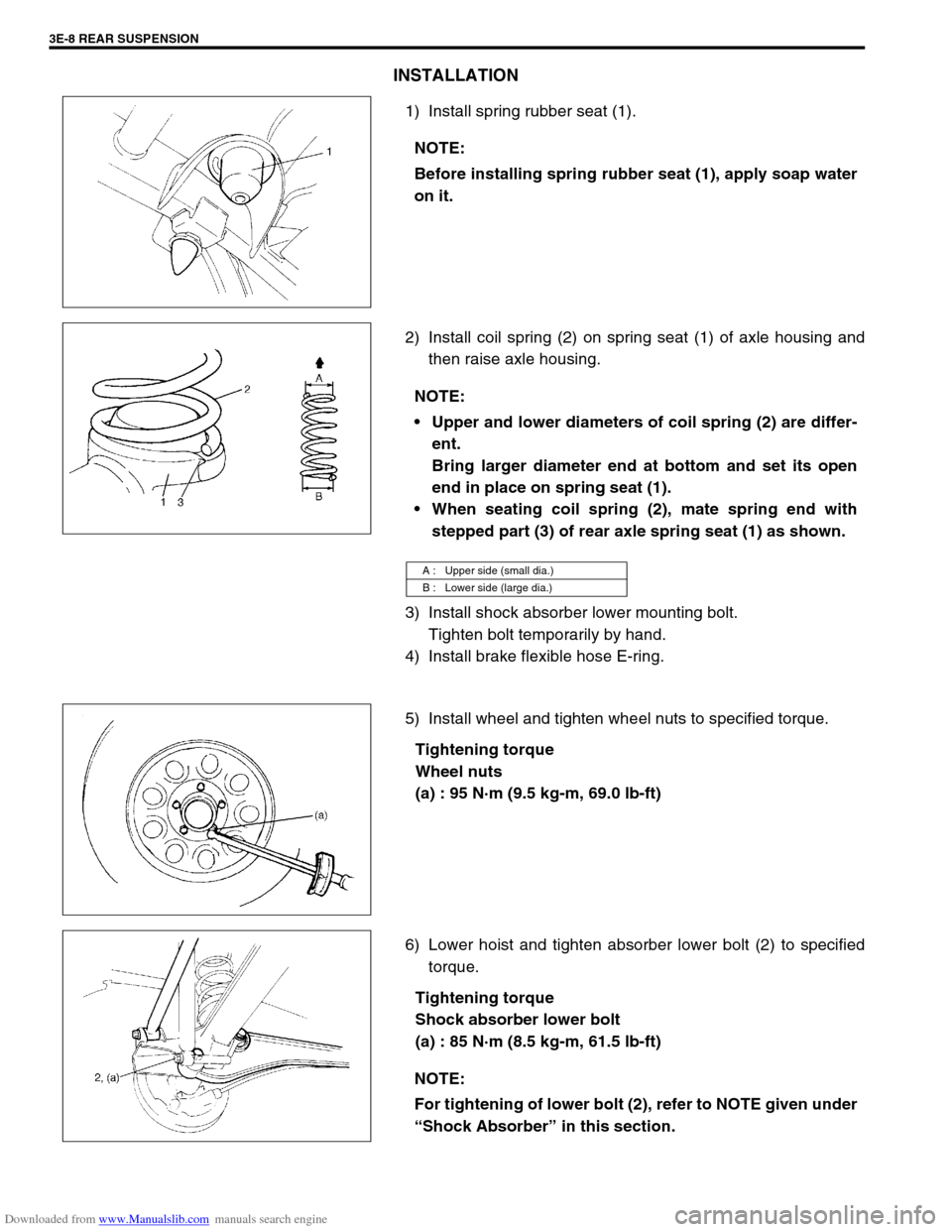
1) Install spring rubber seat (1).
2) Install coil spring (2) on spring seat (1) of axle housing and
then raise axle housing.
3) Install shock absorber lower mounting bolt.
Tighten bolt temporarily by hand.
4) Install brake flexible hose E-ring.
5) Install wheel and tighten wheel nuts to specified torque.
Tightening torque
Wheel nuts
(a) : 95 N·m (9.5 kg-m, 69.0 lb-ft)
6) Lower hoist and tighten absorber lower bolt (2) to specified
torque.
Tightening torque
Shock absorber lower bolt
(a) : 85 N·m (8.5 kg-m, 61.5 lb-ft) NOTE:
Before installing spring rubber seat (1), apply soap water
on it.
NOTE:
Upper and lower diameters of coil spring (2) are differ-
ent.
Bring larger diameter end at bottom and set its open
end in place on spring seat (1).
When seating coil spring (2), mate spring end with
stepped part (3) of rear axle spring seat (1) as shown.
A : Upper side (small dia.)
B : Lower side (large dia.)
NOTE:
For tightening of lower bolt (2), refer to NOTE given under
“Shock Absorber” in this section.
Page 228 of 687
Downloaded from www.Manualslib.com manuals search engine REAR SUSPENSION 3E-9
Bump Stopper
REMOVAL
1) Hoist vehicle.
2) Remove wheel.
3) Remove bump stopper (1) by using special tool.
Special tool
(A) : 09941-66010
INSTALLATION
1) Tighten bump stopper (1) to specified torque by using spe-
cial tool.
Special tool
(A) : 09941-66010
Tightening torque
Bump stopper
(a) : 50 N·m (5.0 kg-m, 36.5 lb-ft)
2) Install wheel and tighten wheel nuts to specified torque.
Tightening torque
Wheel nuts
(a) : 95 N·m (9.5 kg-m, 69.0 lb-ft)
3) Lower hoist.
Lateral Rod
REMOVAL
1) Hoist vehicle.
2) Remove lateral rod mounting bolt (2) and nut (3).
3) Remove lateral rod (1).
Page 229 of 687
Downloaded from www.Manualslib.com manuals search engine 3E-10 REAR SUSPENSION
INSTALLATION
1) Install lateral rod to vehicle body and rear axle housing.
Tighten bolt and nut temporarily by hand.
2) Lower hoist and with vehicle in non-loaded condition, tighten
lateral rod bolt and nut to specified torque.
Tightening torque
Lateral rod bolt and nut
(a) : 90 N·m (9.0 kg-m, 65.0 lb-ft)
Trailing Arm / Bushing
REMOVAL
1) Hoist vehicle.
2) Support rear axle housing (1) by using floor jack (2).
3) Disconnect parking brake cable clamp (1) from trailing arm.
4) Disconnect wheel speed sensor harness clamps (2) from
trailing arm (if equipped with ABS).
5) Remove trailing arm mounting bolts.
6) Remove trailing arm (1).
Page 231 of 687

Downloaded from www.Manualslib.com manuals search engine 3E-12 REAR SUSPENSION
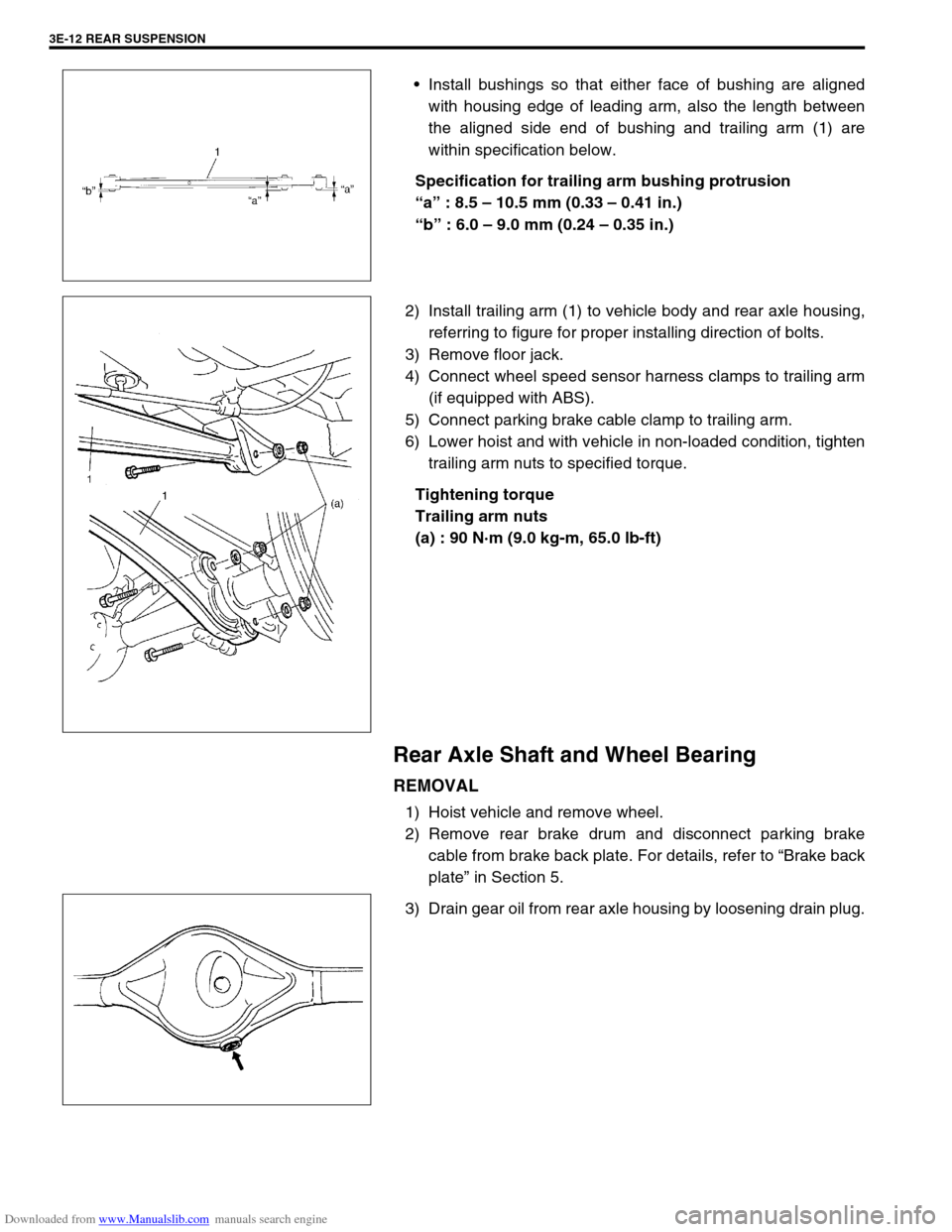
Install bushings so that either face of bushing are aligned
with housing edge of leading arm, also the length between
the aligned side end of bushing and trailing arm (1) are
within specification below.
Specification for trailing arm bushing protrusion
“a” : 8.5 – 10.5 mm (0.33 – 0.41 in.)
“b” : 6.0 – 9.0 mm (0.24 – 0.35 in.)
2) Install trailing arm (1) to vehicle body and rear axle housing,
referring to figure for proper installing direction of bolts.
3) Remove floor jack.
4) Connect wheel speed sensor harness clamps to trailing arm
(if equipped with ABS).
5) Connect parking brake cable clamp to trailing arm.
6) Lower hoist and with vehicle in non-loaded condition, tighten
trailing arm nuts to specified torque.
Tightening torque
Trailing arm nuts
(a) : 90 N·m (9.0 kg-m, 65.0 lb-ft)
Rear Axle Shaft and Wheel Bearing
REMOVAL
1) Hoist vehicle and remove wheel.
2) Remove rear brake drum and disconnect parking brake
cable from brake back plate. For details, refer to “Brake back
plate” in Section 5.
3) Drain gear oil from rear axle housing by loosening drain plug.
Page 235 of 687

Downloaded from www.Manualslib.com manuals search engine 3E-16 REAR SUSPENSION
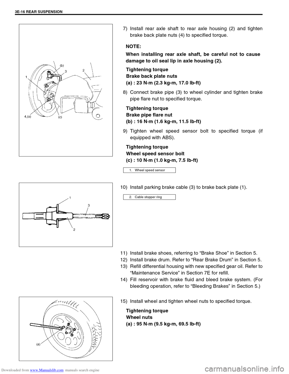
7) Install rear axle shaft to rear axle housing (2) and tighten
brake back plate nuts (4) to specified torque.
Tightening torque
Brake back plate nuts
(a) : 23 N·m (2.3 kg-m, 17.0 lb-ft)
8) Connect brake pipe (3) to wheel cylinder and tighten brake
pipe flare nut to specified torque.
Tightening torque
Brake pipe flare nut
(b) : 16 N·m (1.6 kg-m, 11.5 lb-ft)
9) Tighten wheel speed sensor bolt to specified torque (if
equipped with ABS).
Tightening torque
Wheel speed sensor bolt
(c) : 10 N·m (1.0 kg-m, 7.5 lb-ft)
10) Install parking brake cable (3) to brake back plate (1).
11) Install brake shoes, referring to “Brake Shoe” in Section 5.
12) Install brake drum. Refer to “Rear Brake Drum” in Section 5.
13) Refill differential housing with new specified gear oil. Refer to
“Maintenance Service” in Section 7E for refill.
14) Fill reservoir with brake fluid and bleed brake system. (For
bleeding operation, refer to “Bleeding Brakes” in Section 5.)
15) Install wheel and tighten wheel nuts to specified torque.
Tightening torque
Wheel nuts
(a) : 95 N·m (9.5 kg-m, 69.5 lb-ft) NOTE:
When installing rear axle shaft, be careful not to cause
damage to oil seal lip in axle housing (2).
1. Wheel speed sensor
2. Cable stopper ring
Page 240 of 687

Downloaded from www.Manualslib.com manuals search engine REAR SUSPENSION 3E-21
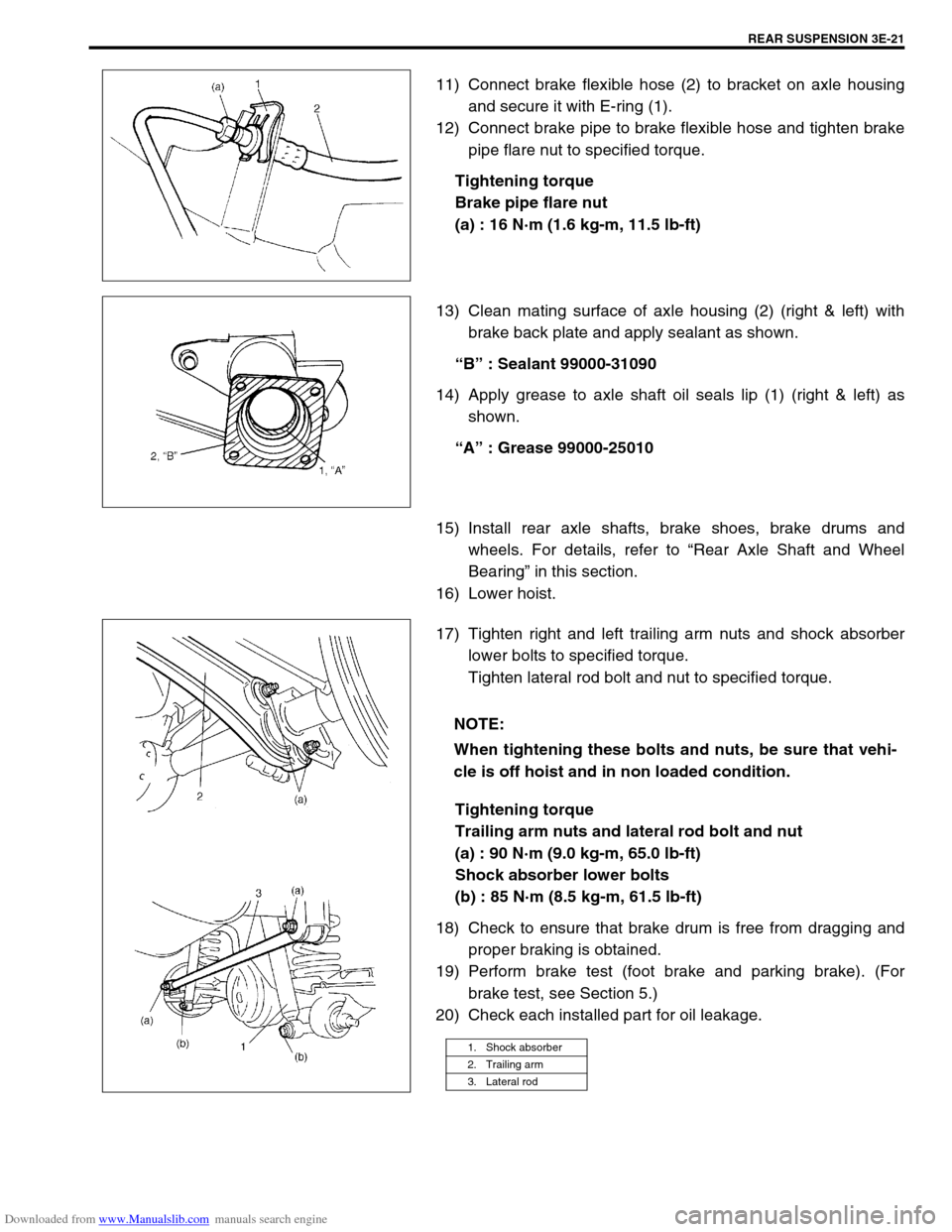
11) Connect brake flexible hose (2) to bracket on axle housing
and secure it with E-ring (1).
12) Connect brake pipe to brake flexible hose and tighten brake
pipe flare nut to specified torque.
Tightening torque
Brake pipe flare nut
(a) : 16 N·m (1.6 kg-m, 11.5 lb-ft)
13) Clean mating surface of axle housing (2) (right & left) with
brake back plate and apply sealant as shown.
“B” : Sealant 99000-31090
14) Apply grease to axle shaft oil seals lip (1) (right & left) as
shown.
“A” : Grease 99000-25010
15) Install rear axle shafts, brake shoes, brake drums and
wheels. For details, refer to “Rear Axle Shaft and Wheel
Bearing” in this section.
16) Lower hoist.
17) Tighten right and left trailing arm nuts and shock absorber
lower bolts to specified torque.
Tighten lateral rod bolt and nut to specified torque.
Tightening torque
Trailing arm nuts and lateral rod bolt and nut
(a) : 90 N·m (9.0 kg-m, 65.0 lb-ft)
Shock absorber lower bolts
(b) : 85 N·m (8.5 kg-m, 61.5 lb-ft)
18) Check to ensure that brake drum is free from dragging and
proper braking is obtained.
19) Perform brake test (foot brake and parking brake). (For
brake test, see Section 5.)
20) Check each installed part for oil leakage.
NOTE:
When tightening these bolts and nuts, be sure that vehi-
cle is off hoist and in non loaded condition.
1. Shock absorber
2. Trailing arm
3. Lateral rod