Page 215 of 687

Downloaded from www.Manualslib.com manuals search engine 3D-42 FRONT SUSPENSION
9) Install right and left axle shafts to axle housing (for 4WD).
Install knuckle to axle housing (for 2WD).
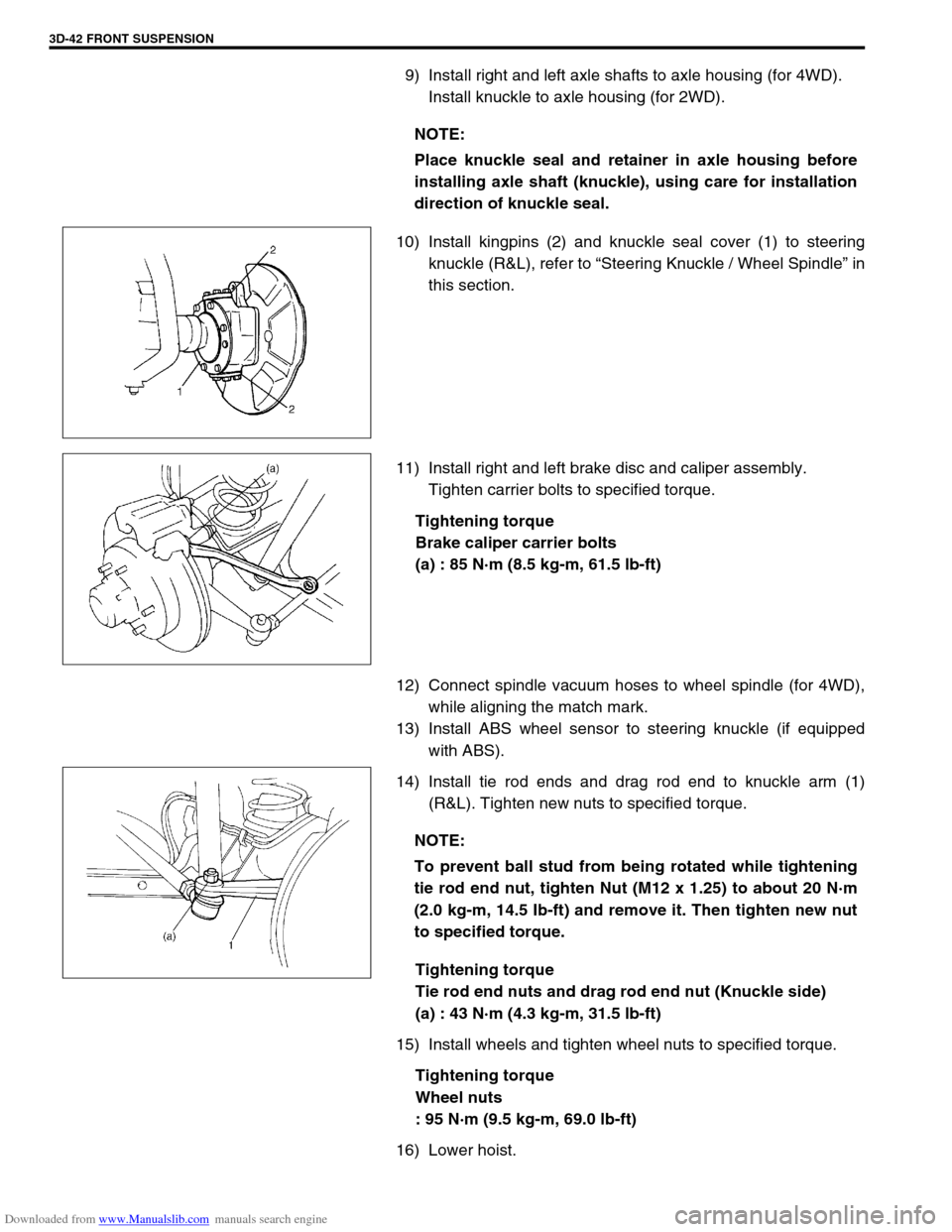
10) Install kingpins (2) and knuckle seal cover (1) to steering
knuckle (R&L), refer to “Steering Knuckle / Wheel Spindle” in
this section.
11) Install right and left brake disc and caliper assembly.
Tighten carrier bolts to specified torque.
Tightening torque
Brake caliper carrier bolts
(a) : 85 N·m (8.5 kg-m, 61.5 lb-ft)
12) Connect spindle vacuum hoses to wheel spindle (for 4WD),
while aligning the match mark.
13) Install ABS wheel sensor to steering knuckle (if equipped
with ABS).
14) Install tie rod ends and drag rod end to knuckle arm (1)
(R&L). Tighten new nuts to specified torque.
Tightening torque
Tie rod end nuts and drag rod end nut (Knuckle side)
(a) : 43 N·m (4.3 kg-m, 31.5 lb-ft)
15) Install wheels and tighten wheel nuts to specified torque.
Tightening torque
Wheel nuts
: 95 N·m (9.5 kg-m, 69.0 lb-ft)
16) Lower hoist.NOTE:
Place knuckle seal and retainer in axle housing before
installing axle shaft (knuckle), using care for installation
direction of knuckle seal.
NOTE:
To prevent ball stud from being rotated while tightening
tie rod end nut, tighten Nut (M12 x 1.25) to about 20 N·m
(2.0 kg-m, 14.5 Ib-ft) and remove it. Then tighten new nut
to specified torque.
Page 216 of 687
Downloaded from www.Manualslib.com manuals search engine FRONT SUSPENSION 3D-43
17) Tighten lateral rod (1) mounting bolt and nut to specified
torque.
Tightening torque
Lateral rod bolt and nut
(a) : 90 N·m (9.0 kg-m, 65.0 lb-ft)
18) Tighten right and left shock absorber lower mounting nuts
and leading arm mounting nuts to specified torque.
Tightening torque
Shock absorber lower nuts and leading arm nuts
(a) : 90 N·m (9.0 kg-m, 65.0 lb-ft)
19) Refill front axle (differential) housing with new specified gear
oil. Refer to “Maintenance Service” in Section 7E for refill.
20) Confirm front end (wheel) alignment referring to “Preliminary
Checks Prior to Adjusting Front Alignment” in Section 3A. NOTE:
When tightening bolt and nut, be sure that vehicle is off
hoist and in non loaded condition.
NOTE:
When tightening these nuts, be sure that vehicle is off
hoist and in non loaded condition.
1. Shock absorber
2. Leading arm
Page 217 of 687

Downloaded from www.Manualslib.com manuals search engine 3D-44 FRONT SUSPENSION
Tightening Torque Specifications
Required Service Material
Fastening partTightening torque
Nm kg-m lb-ft
Stabilizer mount bracket bolt 20 2.0 14.5
Stabilizer ball joint nut 50 5.0 36.5
Shock absorber lock nut 29 2.9 21.0
Shock absorber lower nut 90 9.0 65.0
Brake caliper carrier bolt 85 8.5 61.5
Wheel bearing lock nut 220 22.0 160.0
Wheel bearing lock washer screw 1.5 0.15 1.0
Air locking hub bolt 48 4.8 35.0
Wheel spindle bolt 50 5.0 36.5
Kingpin bolt 25 2.5 18.0
Knuckle seal cover bolt 10 1.0 7.5
Tie-rod end nut
43 4.3 31.5
Drag-rod end nut (Knuckle side)
Lateral rod bolt and nut
90 9.0 65.0
Leading arm nut
Front differential carrier bolt 23 2.3 17.0
Front propeller shaft flange bolt 50 5.0 36.5
Wheel nut 95 9.5 69.0
Vacuum pipe clamp bolt 5.5 0.55 4.0
MaterialRecommended SUZUKI product
(Part Number)Use
Lithium grease SUZUKI SUPER GREASE (A)
(99000-25010)Knuckle seal / axle shaft oil seal
Recess of wheel spindles
Wheel hub oil seal
Wheel bearing
Spindle thrust washer
Spindle bush (inside and flange
part)
Spindle oil seal
SUZUKI SUPER GREASE (C)
(99000-25030)Kingpin bearing
Axle shaft joint (for 4WD)
Sealant SUZUKI BOND NO. 1215
(99000-31110)Mating surfaces of wheel spindle
and knuckle
Mating surface of differential carrier
and axle housing
Sealing compound SUZUKI SEALING COMPOUND
366E
(99000-31090)Mating surface of wheel spindle and
knuckle
Kingpin
Mating surfaces of hub cap and
wheel hub
Page 218 of 687
Downloaded from www.Manualslib.com manuals search engine FRONT SUSPENSION 3D-45
Special Tool
09917-47910 09913-50121 09913-65210 09913-75520
Vacuum pump gauge Oil seal remover Tie rod end remover Bearing installer
09951-76010 09924-74510 09942-15510 09943-35511 or 09943-
35512
Bearing installer Bearing installer handle Sliding hammer Brake drum remover
09944-66010 09944-68510 09951-16050 09944-77020
Wheel hub / knuckle oil
seal installerBearing installer attach-
mentWheel bearing tightening
toolRing nut wrench
09944-78210 09917-88210 09916-58210 09922-55131
Bearing installer support Valve guide installer
attachmentValve guide installer han-
dleBearing installer
Page 241 of 687

Downloaded from www.Manualslib.com manuals search engine 3E-22 REAR SUSPENSION
Tightening Torque Specifications
Required Service Materials
Fastening portionTightening torque
Nm kg-m lb-ft
Shock absorber upper and lower bolt 85 8.5 61.5
Bump stopper 50 5.0 36.5
Lateral rod bolt and nut
90 9.0 65.0
Trailing arm nut (Front and Rear)
Brake back plate nut 23 2.3 17.0
Brake pipe flare nut 16 1.6 11.5
Rear differential carrier bolt 23 2.3 17.0
Rear propeller shaft bolt (Differential case side) 50 5.0 36.5
Rear propeller shaft bolt (Shaft No.3 transfer case side) 33 3.3 24.0
Wheel nut 95 9.5 69.0
Wheel speed sensor bolt and harness clamp bolt 10 1.0 7.5
MaterialRecommended SUZUKI product
(Part Number)Use
Lithium greaseSUZUKI SUPER GREASE A
(99000-25010)Oil seal lip
SealantSUZUKI BOND NO. 1215
(99000-31110)Joint seam of differential carrier and
axle housing
Water tight sealantSEALING COMPOUND 366E
(99000-31090)To apply to mating surfaces of brake
back plate and rear axle.
Gear oilFor gear oil information, refer to “Mainte-
nance Service” in Section 7E of this manual.Differential gear
(Rear axle housing)
Page 260 of 687

Downloaded from www.Manualslib.com manuals search engine PROPELLER SHAFTS 4B-7
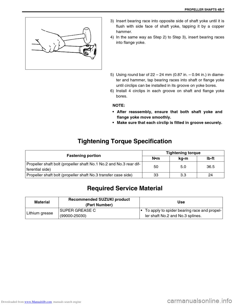
3) Insert bearing race into opposite side of shaft yoke until it is
flush with side face of shaft yoke, tapping it by a copper
hammer.
4) In the same way as Step 2) to Step 3), insert bearing races
into flange yoke.
5) Using round bar of 22 – 24 mm (0.87 in. – 0.94 in.) in diame-
ter and hammer, tap bearing races into shaft or flange yoke
until circlips can be installed in its groove on yoke bores.
6) Install 4 circlips in each groove on shaft and flange yoke
bores.
Tightening Torque Specification
Required Service Material
NOTE:
After reassembly, ensure that both shaft yoke and
flange yoke move smoothly.
Make sure that each circlip is fitted in groove securely.
Fastening portionTightening torque
Nm kg-m lb-ft
Propeller shaft bolt (propeller shaft No.1 No.2 and No.3 rear dif-
ferential side)50 5.0 36.5
Propeller shaft bolt (propeller shaft No.3 transfer case side) 33 3.3 24
MaterialRecommended SUZUKI product
(Part Number)Use
Lithium greaseSUPER GREASE C
(99000-25030)To apply to spider bearing race and propel-
ler shaft No.2 and No.3 splines.
Page 269 of 687

Downloaded from www.Manualslib.com manuals search engine 5-8 BRAKES
Brake Pedal Free Height Adjustment
1) Check brake pedal free height.
If it is not within specification, check and adjust following item
2) and 3).
Brake pedal free height “a” from wall
LH steering vehicle : 221 – 227 mm (8.70 – 8.94 in.)
RH steering vehicle : 217 – 223 mm (8.54 – 8.78 in.)
2) Check measurement between booster mounting surface and
center of clevis pin hole. When booster push rod clevis has
been reinstalled, it is important that the measurement is
adjusted. (Refer to “Brake Booster Inspection and Adjust-
ment” in this section.)
3) Check stop light switch position. Adjust it if it is out of specifi-
cation.
Brake Pedal Play Check
Pedal play should be within specification below.
If out of specification, check stop light switch for proper installation
position and adjust if necessary.
Also check pedal shaft bolt and master cylinder pin installation for
looseness and replace if defective.
Brake pedal play “a” : 1 – 8 mm (0.04 – 0.31 in.)
Stop Light Switch Adjustment
Adjustment should be made as follows when installing switch. Pull
up brake pedal toward you and while holding it there, adjust
switch position so that clearance between end of thread and
brake pedal is specified. Then tighten lock nut to specified torque.
Clearance between brake pedal and stop light switch
“c” : 1.5 – 2.0 mm (0.06 – 0.08 in.)
Tightening torque
Stop light switch lock nut
(a) : 6.5 N·m (0.65 kg-m, 4.7 lb-ft)
Page 270 of 687

Downloaded from www.Manualslib.com manuals search engine BRAKES 5-9
Excessive Pedal Travel Check
1) Start engine.
2) Depress brake pedal a few times.
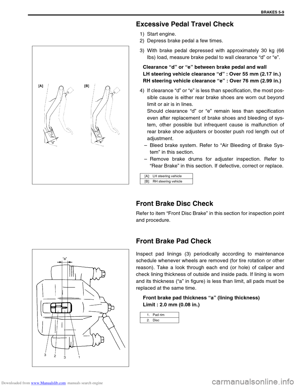
3) With brake pedal depressed with approximately 30 kg (66
Ibs) load, measure brake pedal to wall clearance “d” or “e”.
Clearance “d” or “e” between brake pedal and wall
LH steering vehicle clearance “d” : Over 55 mm (2.17 in.)
RH steering vehicle clearance “e” : Over 76 mm (2.99 in.)
4) If clearance “d” or “e” is less than specification, the most pos-
sible cause is either rear brake shoes are worn out beyond
limit or air is in lines.
Should clearance “d” or “e” remain less than specification
even after replacement of brake shoes and bleeding of sys-
tem, other possible but infrequent cause is malfunction of
rear brake shoe adjusters or booster push rod length out of
adjustment.
–Bleed brake system. Refer to “Air Bleeding of Brake Sys-
tem” in this section.
–Remove brake drums for adjuster inspection. Refer to
“Rear Brake” in this section. If defective, correct or replace.
Front Brake Disc Check
Refer to item “Front Disc Brake” in this section for inspection point
and procedure.
Front Brake Pad Check
Inspect pad linings (3) periodically according to maintenance
schedule whenever wheels are removed (for tire rotation or other
reason). Take a look through each end (or hole) of caliper and
check lining thickness of outside and inside pads. If lining is worn
and its thickness (“a” in figure) is less than limit, all pads must be
replaced at the same time.
Front brake pad thickness “a” (lining thickness)
Limit : 2.0 mm (0.08 in.)
[A]: LH steering vehicle
[B]: RH steering vehicle
1. Pad rim
2. Disc