Page 161 of 687

Downloaded from www.Manualslib.com manuals search engine 3C-8 STEERING WHEEL AND COLUMN
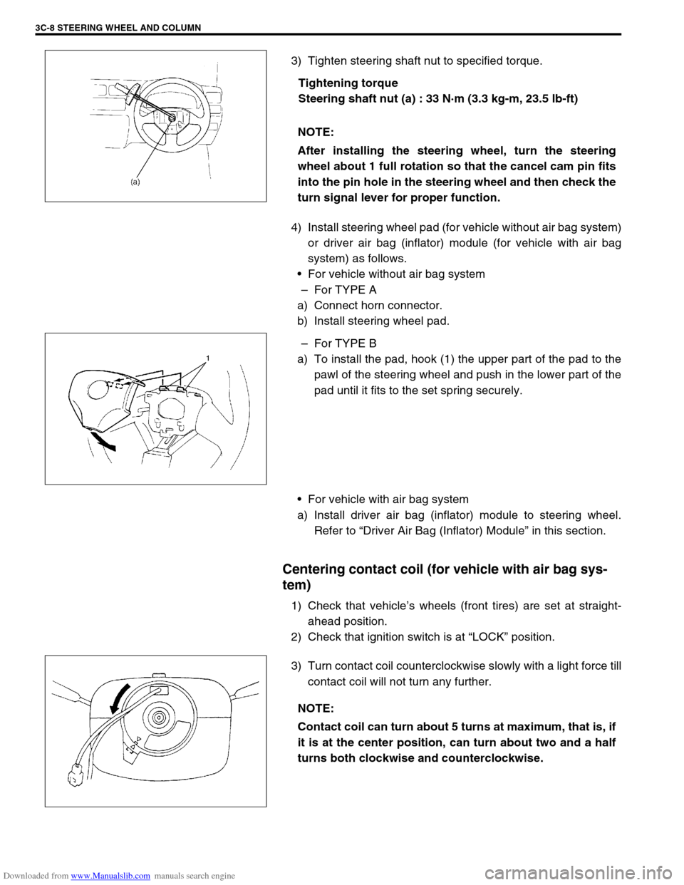
3) Tighten steering shaft nut to specified torque.
Tightening torque
Steering shaft nut (a) : 33 N·m (3.3 kg-m, 23.5 lb-ft)
4) Install steering wheel pad (for vehicle without air bag system)
or driver air bag (inflator) module (for vehicle with air bag
system) as follows.
For vehicle without air bag system
–For TYPE A
a) Connect horn connector.
b) Install steering wheel pad.
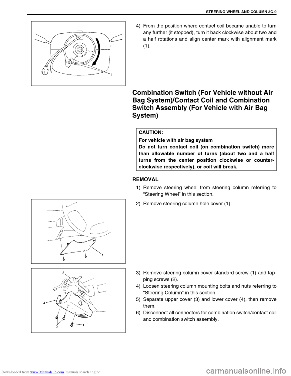
–For TYPE B
a) To install the pad, hook (1) the upper part of the pad to the
pawl of the steering wheel and push in the lower part of the
pad until it fits to the set spring securely.
For vehicle with air bag system
a) Install driver air bag (inflator) module to steering wheel.
Refer to “Driver Air Bag (Inflator) Module” in this section.
Centering contact coil (for vehicle with air bag sys-
tem)
1) Check that vehicle’s wheels (front tires) are set at straight-
ahead position.
2) Check that ignition switch is at “LOCK” position.
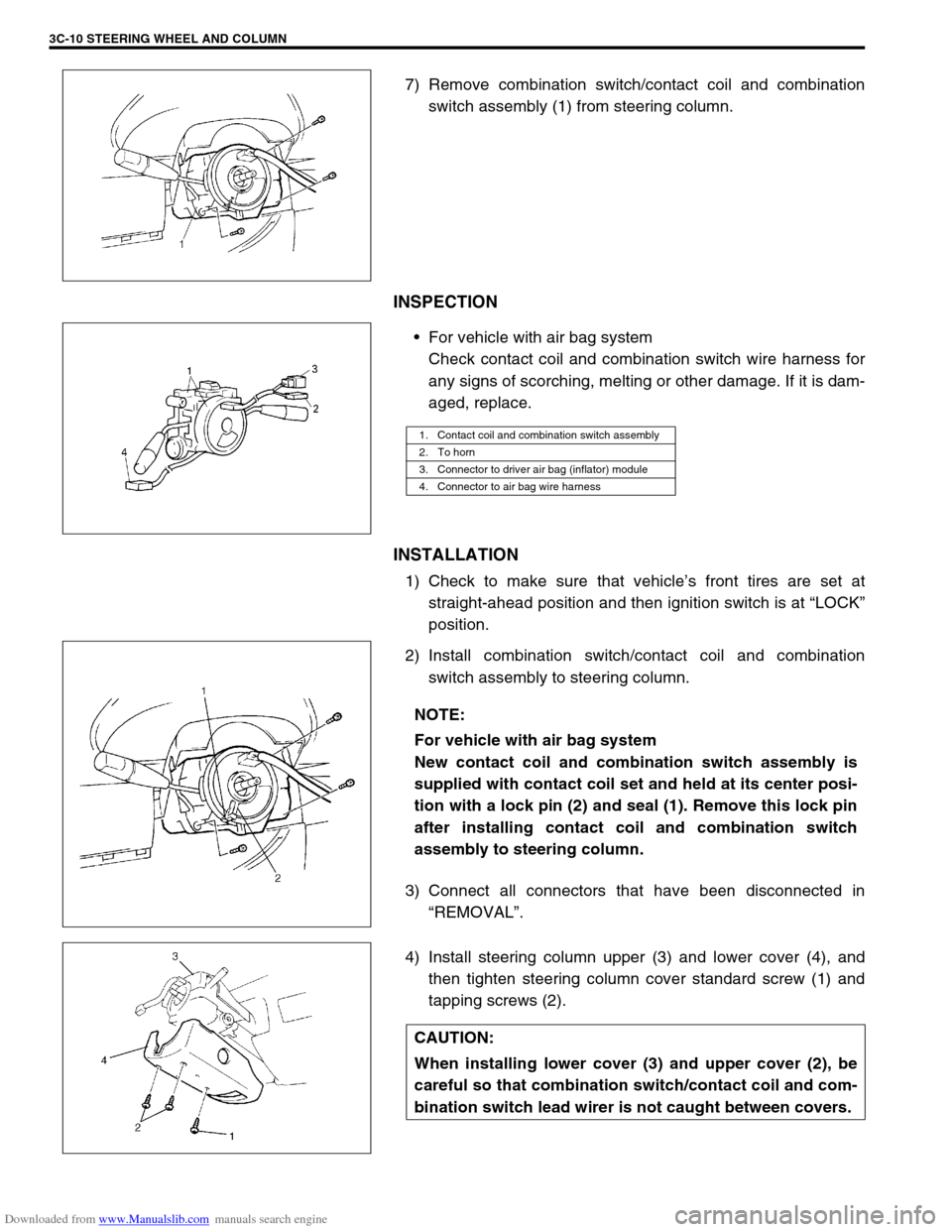
3) Turn contact coil counterclockwise slowly with a light force till
contact coil will not turn any further. NOTE:
After installing the steering wheel, turn the steering
wheel about 1 full rotation so that the cancel cam pin fits
into the pin hole in the steering wheel and then check the
turn signal lever for proper function.
NOTE:
Contact coil can turn about 5 turns at maximum, that is, if
it is at the center position, can turn about two and a half
turns both clockwise and counterclockwise.
Page 162 of 687

Downloaded from www.Manualslib.com manuals search engine STEERING WHEEL AND COLUMN 3C-9
4) From the position where contact coil became unable to turn
any further (it stopped), turn it back clockwise about two and
a half rotations and align center mark with alignment mark
(1).
Combination Switch (For Vehicle without Air
Bag System)/Contact Coil and Combination
Switch Assembly (For Vehicle with Air Bag
System)
REMOVAL
1) Remove steering wheel from steering column referring to
“Steering Wheel” in this section.
2) Remove steering column hole cover (1).
3) Remove steering column cover standard screw (1) and tap-
ping screws (2).
4) Loosen steering column mounting bolts and nuts referring to
“Steering Column” in this section.
5) Separate upper cover (3) and lower cover (4), then remove
them.
6) Disconnect all connectors for combination switch/contact coil
and combination switch assembly.
CAUTION:
For vehicle with air bag system
Do not turn contact coil (on combination switch) more
than allowable number of turns (about two and a half
turns from the center position clockwise or counter-
clockwise respectively), or coil will break.
Page 163 of 687

Downloaded from www.Manualslib.com manuals search engine 3C-10 STEERING WHEEL AND COLUMN
7) Remove combination switch/contact coil and combination
switch assembly (1) from steering column.
INSPECTION
For vehicle with air bag system
Check contact coil and combination switch wire harness for
any signs of scorching, melting or other damage. If it is dam-
aged, replace.
INSTALLATION
1) Check to make sure that vehicle’s front tires are set at
straight-ahead position and then ignition switch is at “LOCK”
position.
2) Install combination switch/contact coil and combination
switch assembly to steering column.
3) Connect all connectors that have been disconnected in
“REMOVAL”.
4) Install steering column upper (3) and lower cover (4), and
then tighten steering column cover standard screw (1) and
tapping screws (2).
1. Contact coil and combination switch assembly
2. To horn
3. Connector to driver air bag (inflator) module
4. Connector to air bag wire harness
NOTE:
For vehicle with air bag system
New contact coil and combination switch assembly is
supplied with contact coil set and held at its center posi-
tion with a lock pin (2) and seal (1). Remove this lock pin
after installing contact coil and combination switch
assembly to steering column.
CAUTION:
When installing lower cover (3) and upper cover (2), be
careful so that combination switch/contact coil and com-
bination switch lead wirer is not caught between covers.
Page 165 of 687

Downloaded from www.Manualslib.com manuals search engine 3C-12 STEERING WHEEL AND COLUMN
REMOVAL
1) Disconnect negative battery cable at battery terminal.
2) For vehicle equipped with air bag system, disable air bag
system referring to “Disabling Air Bag System” in Section
10B.
3) If necessary, remove steering wheel and combination switch
assembly referring to “Steering Wheel” and “Combination
switch/Contact Coil and Combination Switch Assembly” in
this section.
If not removing steering wheel and/or combination switch
assembly, perform the following procedure.
a) Turn steering wheel so that vehicle’s front tires are at
straight ahead position.
b) Turn ignition switch to “LOCK” position and remove key.
4) Remove steering column hole cover (1).
5) Disconnect all connectors of the following parts.
Combination switch/contact coil and combination switch
assembly.
Ignition switch.
Immobilizer control system parts (if equipped).
6) Remove joint bolt (steering column side) (3) and loosen joint
bolt (steering gear box side).
7) Remove steering column mounting nuts (2) and bolts (1).WARNING:
For vehicle with air bag system
Never rest a steering column assembly on the steering
wheel with the air bag (inflator) module face down and
column vertical. Otherwise, personal injury may result.
Page 168 of 687

Downloaded from www.Manualslib.com manuals search engine STEERING WHEEL AND COLUMN 3C-15
4) Insert steering lower shaft (1) to steering shaft.
5) Put the steering column upper cover (3) on top of the steer-
ing column (2), if necessary and then tighten steering col-
umn mounting nuts (5) and bolts (4) by hand.
6) Tighten mounting nuts (5) first and then mounting bolts (4) to
specified torque.
Tightening torque
Steering column mounting bolts and nuts
(a) : 14 N·m (1.4 kg-m, 10.5 lb-ft)
7) Tighten steering column side joint bolt (1) first, and then
tighten steering gear box side joint bolt (2).
Tightening torque
Steering shaft joint bolts (b) : 25 N·m (2.5 kg-m, 18.0 lb-ft)
8) If combination switch is removed, install combination switch
referring to “Combination Switch/Contact Coil and Combina-
tion Switch Assembly” in this section.
9) Connect all connectors that have been removed in
“removal”.
10) Install steering column hole cover (1).
11) If steering wheel is removed, install steering wheel referring
to “Steering Wheel” in this section.
12) If the vehicle equipped with air bag system, enable air bag
system referring to “Enabling Air Bag System” in Section
10B.
13) Connect negative battery cable.
Steering Lock Assembly (Ignition Switch)
REMOVAL
1) Remove steering column (1) referring to “Steering Column”
in this section.
2. Steering lock
Page 297 of 687
Downloaded from www.Manualslib.com manuals search engine 5-36 BRAKES
Master Cylinder
Master Cylinder Reservoir
REMOVAL
1) Disconnect reservoir lead wire at coupler.
2) Clean outside of reservoir (1).
3) Take out fluid with syringe or such.
4) Remove reservoir connector pin (2) by using special tool.
Special tool
(A) : 09922-85811
Remove reservoir (1).
CAUTION:
Brake fluid is extremely damaging to paint.
Do not allow brake fluid to get on painted surfaces.
2. Connector pin
3. Grommets
Page 316 of 687
Downloaded from www.Manualslib.com manuals search engine BRAKES 5-55
Special Tool
09900-20205 09900-20602 09900-20701 09956-02210
Micrometer (0 – 25 mm) Dial gauge (1/1000 mm) Magnetic stand Brake circuit plug
09922-85811 09942-15510 09943-35511 09950-78220
Connector pin remover Sliding hammer Brake drum remover
(Front wheel hub
remover)Flare nut wrench (10 mm)
09950-96010 09952-16010 09956-02310
Booster piston rod gauge Booster piston rod
adjusterFluid pressure gauge
Page 320 of 687

Downloaded from www.Manualslib.com manuals search engine ANTILOCK BRAKE SYSTEM (ABS) 5E-3
System Schematic
1. Wheel speed sensor (Right front) 7. Wheel speed sensor (Left rear) 13. ABS hydraulic unit
2. Stop lamp switch 8.“ABS” warning lamp 14. G sensor
3. ABS control module 9. ABS pump motor transistor 15. Data link connector
4. Wheel speed sensor (Right rear) 10. ABS solenoid valve transistor 16. ABS hydraulic unit / control module assembly
5. Monitor connector 11. Proportioning valve 17. 4WD switch (for 4WD model only)
6. ABS lamp driver module 12. Wheel speed sensor (Left front)
INPUTOUTPUT
ABS control
module Wheel speed sensor (RF)
Wheel speed sensor (RR)
Wheel speed sensor (LR)
Wheel speed sensor (LF)
Stop lamp switch
Diag. switch terminal
Battery voltage
4WD switch (for 4WD model only) G sensor
Pump motor
transistor
Fail-safe
transistor
Pump motor
LF hold solenoid
LF release solenoid
RF hold solenoid
RF release solenoid
Rear hold solenoid
Rear release solenoid
“ABS” warning lamp
Idle-up
ECM
Data link connector
ABS hydraulic unit/control
module assembly