Page 170 of 687
Downloaded from www.Manualslib.com manuals search engine STEERING WHEEL AND COLUMN 3C-17
3) Make alignment marks (3) on lower shaft (2) and shaft (col-
umn side) (1) and lower shaft (2) and gear box shaft (gear
box side) (4) for a guide during reinstallation.
4) Remove lower shaft joint bolts.
5) Remove steering lower shaft.
INSTALLATION
1) Be sure that front wheels and steering wheel are in straight
forward state.
2) Insert lower shaft joint into shaft of steering column with
matching marks (3).
3) Align flat part “A” of steering gear box shaft (4) with bolt hole
“B” of lower shaft joint as shown. Then insert lower shaft joint
into steering gear box shaft (4) with matching marks (3).
4) Tighten shaft joint bolt (column side) to specified torque first
and then shaft joint bolt (gear box shaft side) to specified
torque.
Tightening torque
Steering shaft joint bolts (a) : 25 N·m (2.5 kg-m, 18.0 lb-ft)
1. Steering column assembly
2. Steering lower shaft
Page 172 of 687

Downloaded from www.Manualslib.com manuals search engine STEERING WHEEL AND COLUMN 3C-19
6) Check steering shaft joints and shaft for any damages such
as crack, breakage, malfunction or excessive play.
If anything is found faulty, replace as lower joint assembly or
column assembly.
7) Check steering shaft for smooth rotation.
If found defective, replace as column assembly.
8) Check steering shaft and column for bend, cracks or defor-
mation.
If found defective, replace.
Tightening Torque Specifications
Required Service Material
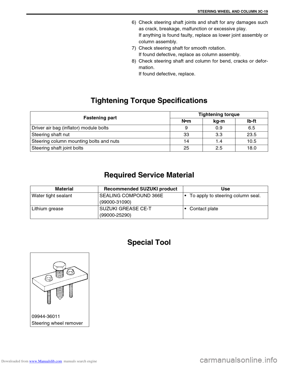
Special Tool
Fastening partTightening torque
Nm kg-m lb-ft
Driver air bag (inflator) module bolts 9 0.9 6.5
Steering shaft nut 33 3.3 23.5
Steering column mounting bolts and nuts 14 1.4 10.5
Steering shaft joint bolts 25 2.5 18.0
Material Recommended SUZUKI product Use
Water tight sealant SEALING COMPOUND 366E
(99000-31090)To apply to steering column seal.
Lithium grease SUZUKI GREASE CE-T
(99000-25290)Contact plate
09944-36011
Steering wheel remover
Page 192 of 687

Downloaded from www.Manualslib.com manuals search engine FRONT SUSPENSION 3D-19
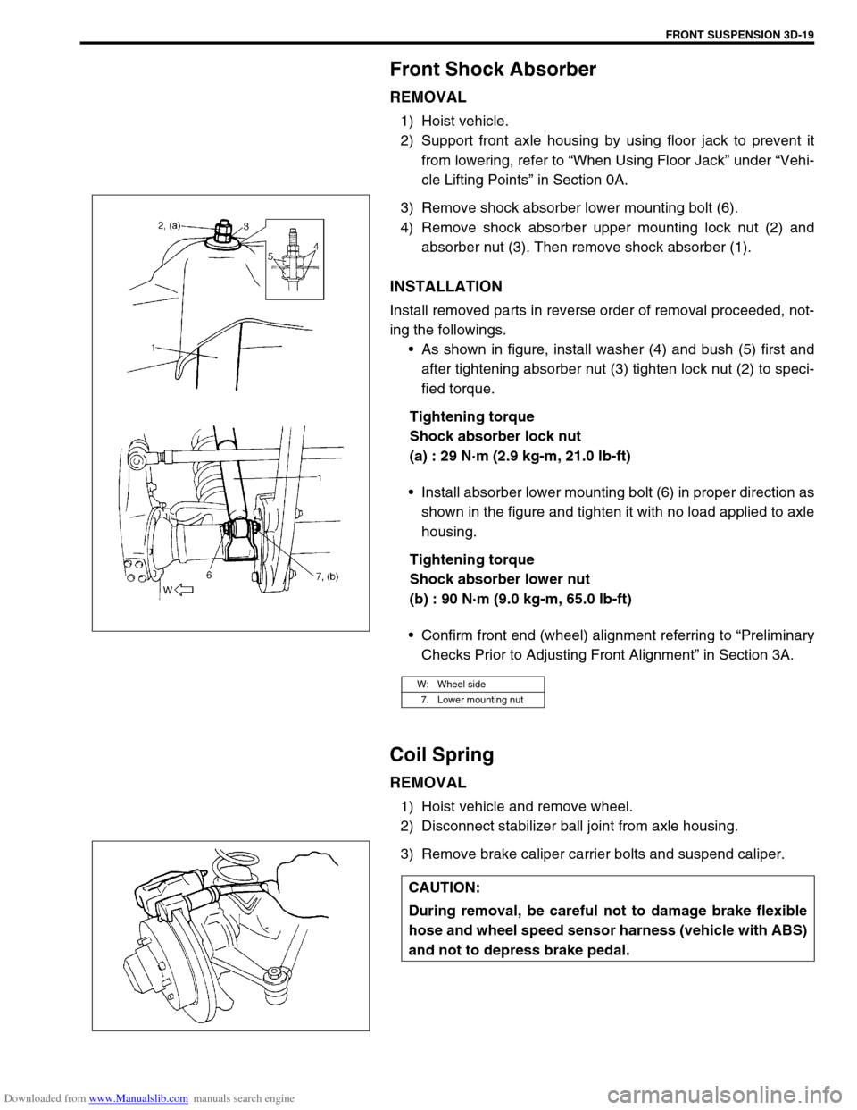
Front Shock Absorber
REMOVAL
1) Hoist vehicle.
2) Support front axle housing by using floor jack to prevent it
from lowering, refer to “When Using Floor Jack” under “Vehi-
cle Lifting Points” in Section 0A.
3) Remove shock absorber lower mounting bolt (6).
4) Remove shock absorber upper mounting lock nut (2) and
absorber nut (3). Then remove shock absorber (1).
INSTALLATION
Install removed parts in reverse order of removal proceeded, not-
ing the followings.
As shown in figure, install washer (4) and bush (5) first and
after tightening absorber nut (3) tighten lock nut (2) to speci-
fied torque.
Tightening torque
Shock absorber lock nut
(a) : 29 N·m (2.9 kg-m, 21.0 lb-ft)
Install absorber lower mounting bolt (6) in proper direction as
shown in the figure and tighten it with no load applied to axle
housing.
Tightening torque
Shock absorber lower nut
(b) : 90 N·m (9.0 kg-m, 65.0 lb-ft)
Confirm front end (wheel) alignment referring to “Preliminary
Checks Prior to Adjusting Front Alignment” in Section 3A.
Coil Spring
REMOVAL
1) Hoist vehicle and remove wheel.
2) Disconnect stabilizer ball joint from axle housing.
3) Remove brake caliper carrier bolts and suspend caliper.
W: Wheel side
7. Lower mounting nut
CAUTION:
During removal, be careful not to damage brake flexible
hose and wheel speed sensor harness (vehicle with ABS)
and not to depress brake pedal.
Page 194 of 687

Downloaded from www.Manualslib.com manuals search engine FRONT SUSPENSION 3D-21
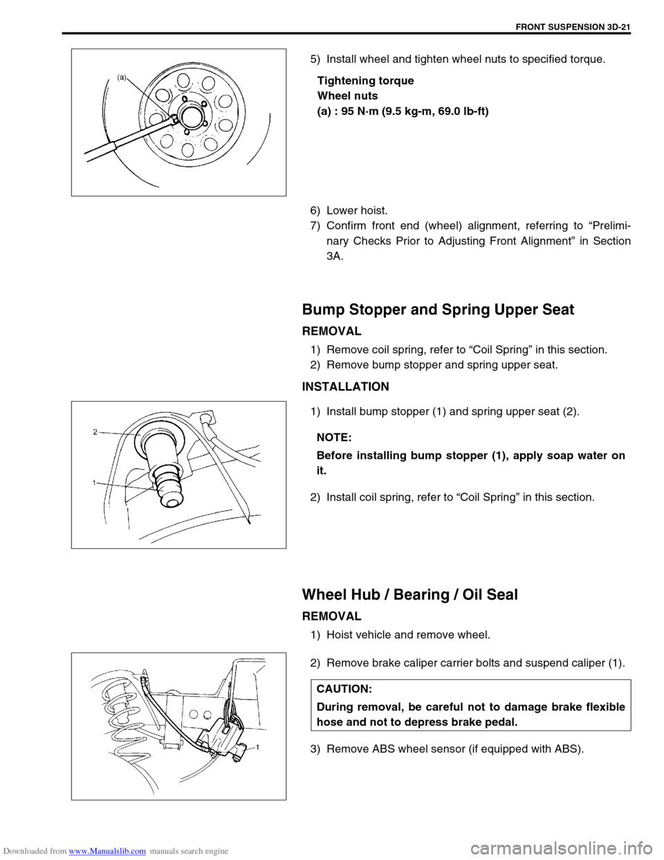
5) Install wheel and tighten wheel nuts to specified torque.
Tightening torque
Wheel nuts
(a) : 95 N·m (9.5 kg-m, 69.0 lb-ft)
6) Lower hoist.
7) Confirm front end (wheel) alignment, referring to “Prelimi-
nary Checks Prior to Adjusting Front Alignment” in Section
3A.
Bump Stopper and Spring Upper Seat
REMOVAL
1) Remove coil spring, refer to “Coil Spring” in this section.
2) Remove bump stopper and spring upper seat.
INSTALLATION
1) Install bump stopper (1) and spring upper seat (2).
2) Install coil spring, refer to “Coil Spring” in this section.
Wheel Hub / Bearing / Oil Seal
REMOVAL
1) Hoist vehicle and remove wheel.
2) Remove brake caliper carrier bolts and suspend caliper (1).
3) Remove ABS wheel sensor (if equipped with ABS).
NOTE:
Before installing bump stopper (1), apply soap water on
it.
CAUTION:
During removal, be careful not to damage brake flexible
hose and not to depress brake pedal.
Page 195 of 687
Downloaded from www.Manualslib.com manuals search engine 3D-22 FRONT SUSPENSION
4) Remove brake disc.
5) Remove front wheel bearing lock nut as follows.
For 2WD model :
a) Remove hub cap.
b) Remove front wheel bearing lock plate (1) by loosening 4
screws (2).
For 4WD model :
a) Remove air locking hub assembly (1).
b) Remove front axle shaft circlip and wheel spindle thrust
washer.
c) Uncaulk front wheel bearing lock nut. NOTE:
If brake disc can not be removed by hand, using 8 mm
bolts.
1. Wheel hub
Page 197 of 687
Downloaded from www.Manualslib.com manuals search engine 3D-24 FRONT SUSPENSION
11) Using hydraulic press (1) and special tool remove wheel
bearing (2).
Special tool
(A) : 09913-75520
12) Remove hub bolts from hub.
INSTALLATION
1) Insert new stud in hub hole. Rotate stud slowly to assure ser-
rations are aligned with those made by original bolt.
2) Using special tool, press-fit wheel bearing (3) until its end
contacts stepped surface of wheel hub (4).
Special tool
(A) : 09944-78210
3) Install bearing circlip.
4) Drive in wheel bearing oil seal (1) by using special tools.
Special tool
(B) : 09944-66010
(C) : 09924-74510
1. Oil hydraulic press
2. Hub bolt
CAUTION:
Press-fit wheel bearing (3) vertically to hub (4).
1. Oil hydraulic press
2. Steel plate
Page 200 of 687

Downloaded from www.Manualslib.com manuals search engine FRONT SUSPENSION 3D-27
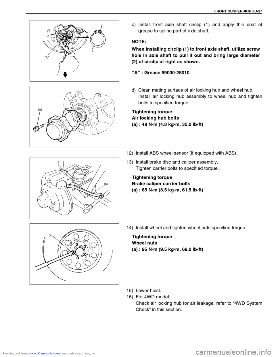
c) Install front axle shaft circlip (1) and apply thin coat of
grease to spline part of axle shaft.
“A” : Grease 99000-25010
d) Clean mating surface of air locking hub and wheel hub.
Install air locking hub assembly to wheel hub and tighten
bolts to specified torque.
Tightening torque
Air locking hub bolts
(a) : 48 N·m (4.8 kg-m, 35.0 lb-ft)
12) Install ABS wheel sensor (if equipped with ABS).
13) Install brake disc and caliper assembly.
Tighten carrier bolts to specified torque.
Tightening torque
Brake caliper carrier bolts
(a) : 85 N·m (8.5 kg-m, 61.5 lb-ft)
14) Install wheel and tighten wheel nuts specified torque.
Tightening torque
Wheel nuts
(a) : 95 N·m (9.5 kg-m, 69.0 lb-ft)
15) Lower hoist.
16) For 4WD model:
Check air locking hub for air leakage, refer to “4WD System
Check” in this section. NOTE:
When installing circlip (1) to front axle shaft, utilize screw
hole in axle shaft to pull it out and bring large diameter
(2) of circlip at right as shown.
Page 201 of 687
Downloaded from www.Manualslib.com manuals search engine 3D-28 FRONT SUSPENSION
Steering Knuckle / Wheel Spindle
REMOVAL
1) Hoist vehicle and remove wheel.
2) Remove wheel hub assembly, refer to “Wheel Hub / Bearing /
Oil Seal” in this section.
3) Disconnect spindle vacuum hoses (1) from wheel spindle (for
4WD).
4) Remove disc dust cover (1) and wheel spindle (2).
5) Remove tie rod end (and drag rod end) nut(s) and discon-
nect tie rod end (and drag rod end) (2) from steering knuckle
(1) with special tool.
Special tool
(A) : 09913-65210
6) Remove knuckle seal cover bolts. Then remove knuckle seal
cover (1), knuckle seal and knuckle seal retainer from
knuckle. CAUTION:
Give match mark to each spindle vacuum hoses before
removing hose.