Page 132 of 687
Downloaded from www.Manualslib.com manuals search engine POWER STEERING (P/S) SYSTEM (If equipped) 3B1-1
6F1
6F2
6G
6H
6K
3B1
7D
7E
7F
7E
7F
8A
8B
8C
8D
8E
9
10
10A
10B
SECTION 3B1
POWER STEERING (P/S) SYSTEM
(If equipped)
CONTENTS
General Description ......................................3B1-2
Diagnosis .......................................................3B1-3
Diagnosis Table .......................................... 3B1-3
Steering Wheel Play Check ........................ 3B1-5
Steering Force Check ................................. 3B1-5
Power Steering Belt Check ......................... 3B1-6
Power Steering Belt Tension Adjustment .... 3B1-6
Power Steering Fluid Level Check .............. 3B1-6
Idle-Up System Check ................................ 3B1-7
Power Steering Fluid Leakage Check ......... 3B1-7Air Bleeding Procedure ............................... 3B1-8
Hydraulic Pressure In P/S Circuit Check .. 3B1-10
On-Vehicle Service ..................................... 3B1-12
Power Steering Belt .................................. 3B1-12
Power Steering (P/S) Pump ...................... 3B1-12
Power Steering (P/S) Gear Box ................ 3B1-18
Tightening Torque Specifications ............. 3B1-21
Required Service Materials ........................ 3B1-21
Special Tools ............................................... 3B1-21 WARNING:
For vehicles equipped with Supplemental Restraint (Air Bag) System :
Service on and around the air bag system components or wiring must be performed only by an
authorized SUZUKI dealer. Refer to “Air Bag System Components and Wiring Location View” under
“General Description” in air bag system section in order to confirm whether you are performing ser-
vice on or near the air bag system components or wiring. Please observe all WARNINGS and “Ser-
vice Precautions” under “On-Vehicle Service” in air bag system section before performing service
on or around the air bag system components or wiring. Failure to follow WARNINGS could result in
unintentional activation of the system or could render the system inoperative. Either of these two
conditions may result in severe injury.
Technical service work must be started at least 90 seconds after the ignition switch is turned to the
“LOCK” position and negative cable is disconnected from the battery. Otherwise, the system may
be activated by reserve energy in the Sensing and Diagnostic Module (SDM).
NOTE:
All steering gear fasteners are important attaching parts in that they could affect the performance of
vital parts and systems, and/or could result in major repair expense. They must be replaced with one
of the same part number or with an equivalent part if replacement becomes necessary. Do not use a
replacement part of lesser quality or substitute design. Torque values must be used as specified dur-
ing reassembly to assure proper retention of these parts.
Page 136 of 687
Downloaded from www.Manualslib.com manuals search engine POWER STEERING (P/S) SYSTEM (If equipped) 3B1-5
Steering Wheel Play Check
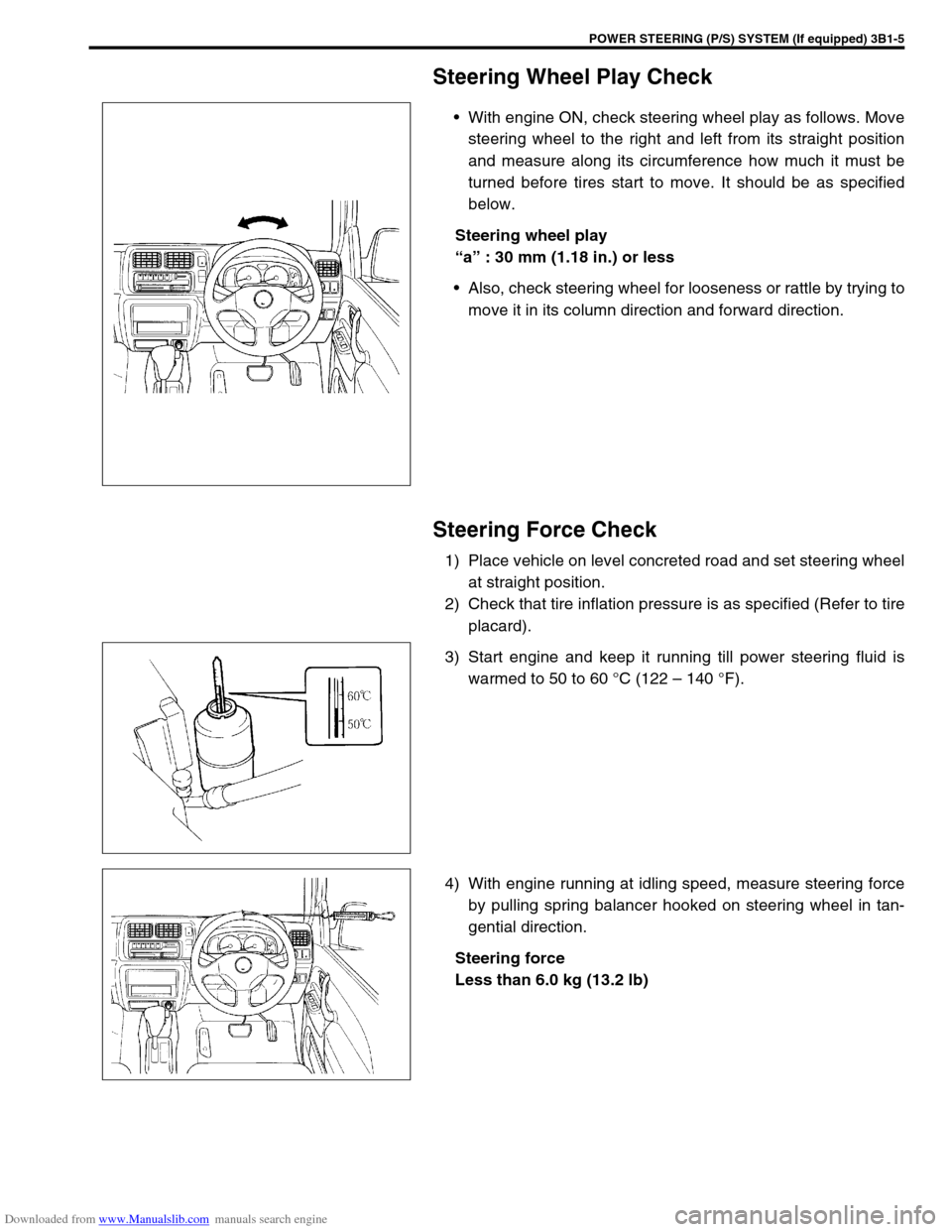
With engine ON, check steering wheel play as follows. Move
steering wheel to the right and left from its straight position
and measure along its circumference how much it must be
turned before tires start to move. It should be as specified
below.
Steering wheel play
“a” : 30 mm (1.18 in.) or less
Also, check steering wheel for looseness or rattle by trying to
move it in its column direction and forward direction.
Steering Force Check
1) Place vehicle on level concreted road and set steering wheel
at straight position.
2) Check that tire inflation pressure is as specified (Refer to tire
placard).
3) Start engine and keep it running till power steering fluid is
warmed to 50 to 60 °C (122 – 140 °F).
4) With engine running at idling speed, measure steering force
by pulling spring balancer hooked on steering wheel in tan-
gential direction.
Steering force
Less than 6.0 kg (13.2 lb)
Page 137 of 687
Downloaded from www.Manualslib.com manuals search engine 3B1-6 POWER STEERING (P/S) SYSTEM (If equipped)
Power Steering Belt Check
INSPECTION
Check that belt is free from any damage and properly fitted
in pulley groove.
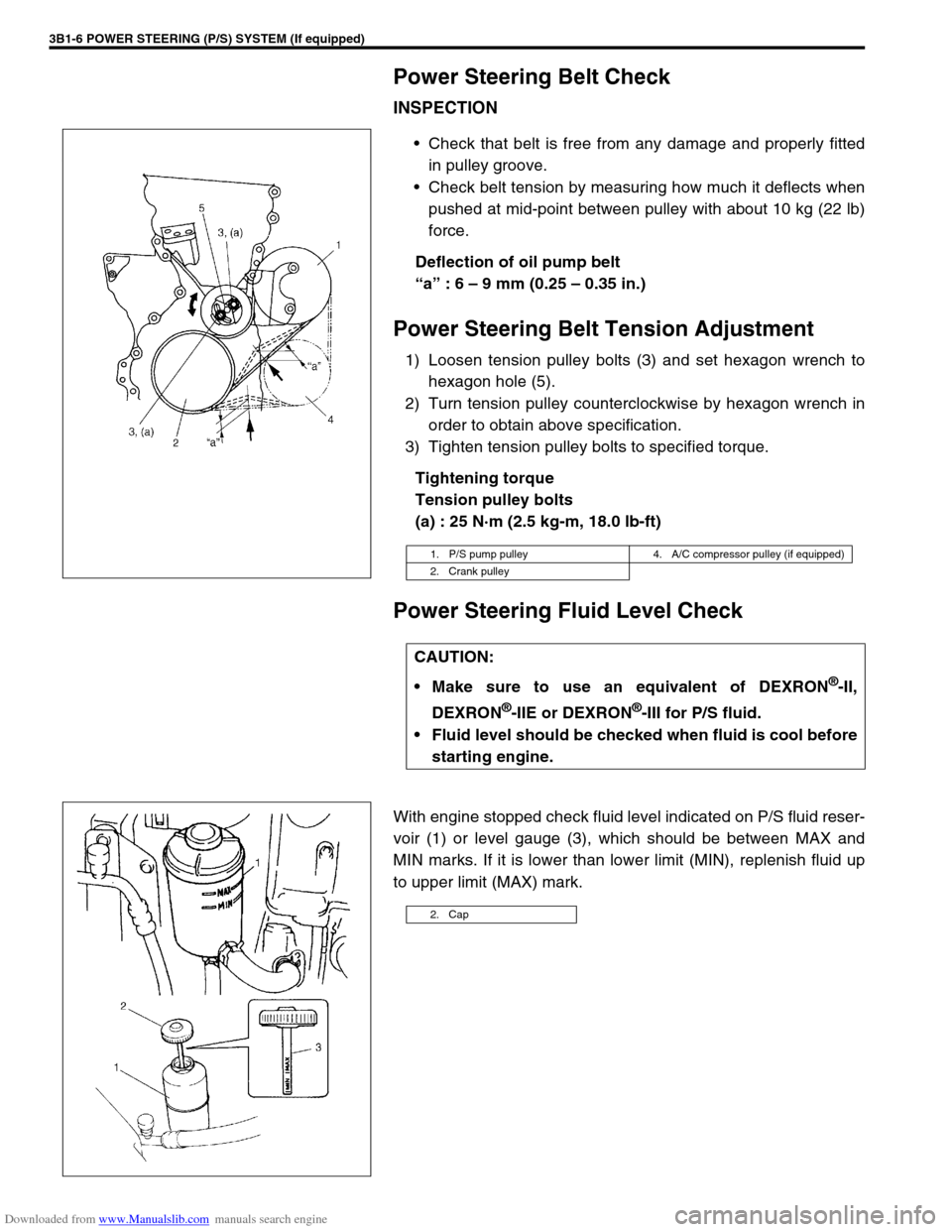
Check belt tension by measuring how much it deflects when
pushed at mid-point between pulley with about 10 kg (22 lb)
force.
Deflection of oil pump belt
“a” : 6 – 9 mm (0.25 – 0.35 in.)
Power Steering Belt Tension Adjustment
1) Loosen tension pulley bolts (3) and set hexagon wrench to
hexagon hole (5).
2) Turn tension pulley counterclockwise by hexagon wrench in
order to obtain above specification.
3) Tighten tension pulley bolts to specified torque.
Tightening torque
Tension pulley bolts
(a) : 25 N·m (2.5 kg-m, 18.0 lb-ft)
Power Steering Fluid Level Check
With engine stopped check fluid level indicated on P/S fluid reser-
voir (1) or level gauge (3), which should be between MAX and
MIN marks. If it is lower than lower limit (MIN), replenish fluid up
to upper limit (MAX) mark.
1. P/S pump pulley 4. A/C compressor pulley (if equipped)
2. Crank pulley
CAUTION:
Make sure to use an equivalent of DEXRON
®-II,
DEXRON
®-IIE or DEXRON®-III for P/S fluid.
Fluid level should be checked when fluid is cool before
starting engine.
2. Cap
Page 138 of 687
Downloaded from www.Manualslib.com manuals search engine POWER STEERING (P/S) SYSTEM (If equipped) 3B1-7
Idle-Up System Check
1) Warm up engine to normal operating temperature.
2) Turn A/C switch OFF, if equipped.
3) Turn steering wheel fully and check idle speed.
Engine idle speed drops a little momentarily when steering wheel is turned fully but returns to its specified
level immediately. If power steering pressure switch connector is connected, check the same with that con-
nector disconnected. Momentary drop of engine idle speed should be less when it is connected than when
disconnected.
Power Steering Fluid Leakage Check
Start engine and turn steering wheel fully to the right and left so that maximum hydraulic pressure is applied to
system. Then visually check gear box, P/S pump and P/S fluid reservoir respectively and each joint of hydraulic
pressure piping for leakage. During this check, however, never keep steering wheel turned fully for longer than
10 seconds.
Page 150 of 687
Downloaded from www.Manualslib.com manuals search engine POWER STEERING (P/S) SYSTEM (If equipped) 3B1-19
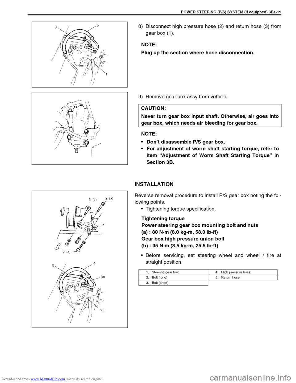
8) Disconnect high pressure hose (2) and return hose (3) from
gear box (1).
9) Remove gear box assy from vehicle.
INSTALLATION
Reverse removal procedure to install P/S gear box noting the fol-
lowing points.
Tightening torque specification.
Tightening torque
Power steering gear box mounting bolt and nuts
(a) : 80 N·m (8.0 kg-m, 58.0 lb-ft)
Gear box high pressure union bolt
(b) : 35 N·m (3.5 kg-m, 25.5 lb-ft)
Before servicing, set steering wheel and wheel / tire at
straight position. NOTE:
Plug up the section where hose disconnection.
CAUTION:
Never turn gear box input shaft. Otherwise, air goes into
gear box, which needs air bleeding for gear box.
NOTE:
Don’t disassemble P/S gear box.
For adjustment of worm shaft starting torque, refer to
item “Adjustment of Worm Shaft Starting Torque” in
Section 3B.
1. Steering gear box 4. High pressure hose
2. Bolt (long) 5. Return hose
3. Bolt (short)
Page 183 of 687
Downloaded from www.Manualslib.com manuals search engine 3D-10 FRONT SUSPENSION
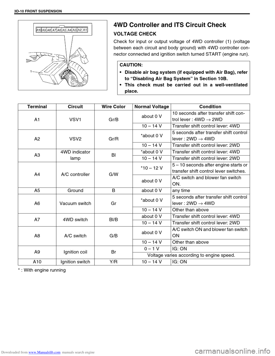
4WD Controller and ITS Circuit Check
VOLTAGE CHECK
Check for input or output voltage of 4WD controller (1) (voltage
between each circuit and body ground) with 4WD controller con-
nector connected and ignition switch turned START (engine run).
* : With engine runningCAUTION:
Disable air bag system (if equipped with Air Bag), refer
to “Disabling Air Bag System” in Section 10B.
This check must be carried out in a well-ventilated
place.
Terminal Circuit Wire Color Normal Voltage Condition
A1 VSV1 Gr/Babout 0 V10 seconds after transfer shift con-
trol lever : 4WD → 2WD
10 – 14 V Transfer shift control lever: 4WD
A2 VSV2 Gr/R*about 0 V5 seconds after transfer shift control
lever : 2WD → 4WD
10 – 14 V Transfer shift control lever: 2WD
A34WD indicator
lampBl*about 0 V Transfer shift control lever: 4WD
10 – 14 V Transfer shift control lever: 2WD
A4 A/C controller G/W*10 – 12 V5 – 10 seconds after engine starts or
transfer shift control lever switches.
about 0 VA/C switch and blower fan switch
ON.
A5 Ground B about 0 V any time
A6 Vacuum switch Gr*about 0 V5 seconds after transfer shift control
lever : 2WD → 4WD
10 – 14 V Other than above
A7 4WD switch Bl/Babout 0 V Transfer shift control lever: 4WD
10 – 14 V Transfer shift control lever: 2WD
A8 A/C switch G/Babout 0 VA/C switch ON and blower fan switch
ON
10 – 14 V Other than above
A9 Ignition coil Br0 – 1 V IG: ON
Voltage varies according to engine speed.
A10 Ignition switch Y/R 10 – 14 V IG: ON
Page 184 of 687
Downloaded from www.Manualslib.com manuals search engine FRONT SUSPENSION 3D-11
4WD Control System Check
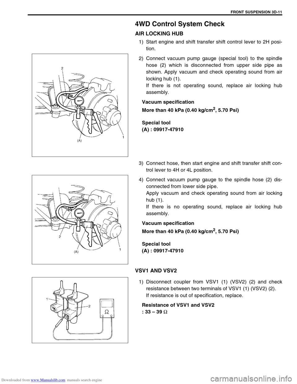
AIR LOCKING HUB
1) Start engine and shift transfer shift control lever to 2H posi-
tion.
2) Connect vacuum pump gauge (special tool) to the spindle
hose (2) which is disconnected from upper side pipe as
shown. Apply vacuum and check operating sound from air
locking hub (1).
If there is not operating sound, replace air locking hub
assembly.
Vacuum specification
More than 40 kPa (0.40 kg/cm
2, 5.70 Psi)
Special tool
(A) : 09917-47910
3) Connect hose, then start engine and shift transfer shift con-
trol lever to 4H or 4L position.
4) Connect vacuum pump gauge to the spindle hose (2) dis-
connected from lower side pipe.
Apply vacuum and check operating sound from air locking
hub (1).
If there is no operating sound, replace air locking hub
assembly.
Vacuum specification
More than 40 kPa (0.40 kg/cm
2, 5.70 Psi)
Special tool
(A) : 09917-47910
VSV1 AND VSV2
1) Disconnect coupler from VSV1 (1) (VSV2) (2) and check
resistance between two terminals of VSV1 (1) (VSV2) (2).
If resistance is out of specification, replace.
Resistance of VSV1 and VSV2
: 33 – 39
Ω
Page 255 of 687
Downloaded from www.Manualslib.com manuals search engine 4B-2 PROPELLER SHAFTS
General Description
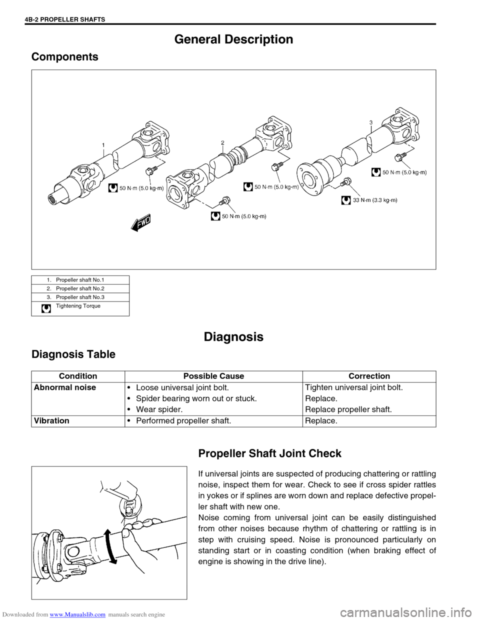
Components
Diagnosis
Diagnosis Table
Propeller Shaft Joint Check
If universal joints are suspected of producing chattering or rattling
noise, inspect them for wear. Check to see if cross spider rattles
in yokes or if splines are worn down and replace defective propel-
ler shaft with new one.
Noise coming from universal joint can be easily distinguished
from other noises because rhythm of chattering or rattling is in
step with cruising speed. Noise is pronounced particularly on
standing start or in coasting condition (when braking effect of
engine is showing in the drive line).
1. Propeller shaft No.1
2. Propeller shaft No.2
3. Propeller shaft No.3
Tightening Torque
Condition Possible Cause Correction
Abnormal noise
Loose universal joint bolt.
Spider bearing worn out or stuck.
Wear spider.Tighten universal joint bolt.
Replace.
Replace propeller shaft.
Vibration
Performed propeller shaft. Replace.