Page 237 of 687
Downloaded from www.Manualslib.com manuals search engine 3E-18 REAR SUSPENSION
Rear Axle Housing
REMOVAL
1) Hoist vehicle and remove wheels.
2) Remove rear axle shaft, refer to “Rear Axle Shaft and Wheel
Bearing” in this section.
3) Disconnect brake pipe (3) from flexible hose (1) and remove
E-ring (2).
4) Remove brake pipe clamps and pipes from axle housing.
5) For jobs hereafter, support rear axle housing (2) by using
floor jack (1) under axle housing (2).
6) Remove LSPV stay from axle housing (if equipped with
LSPV).
7) Before removing propeller shaft (2), give match marks (1) on
joint flange and propeller shaft (2) as shown.
Remove propeller shaft (2).
8) Remove differential carrier assembly (3).
9) Remove lateral rod (1).
Page 239 of 687

Downloaded from www.Manualslib.com manuals search engine 3E-20 REAR SUSPENSION
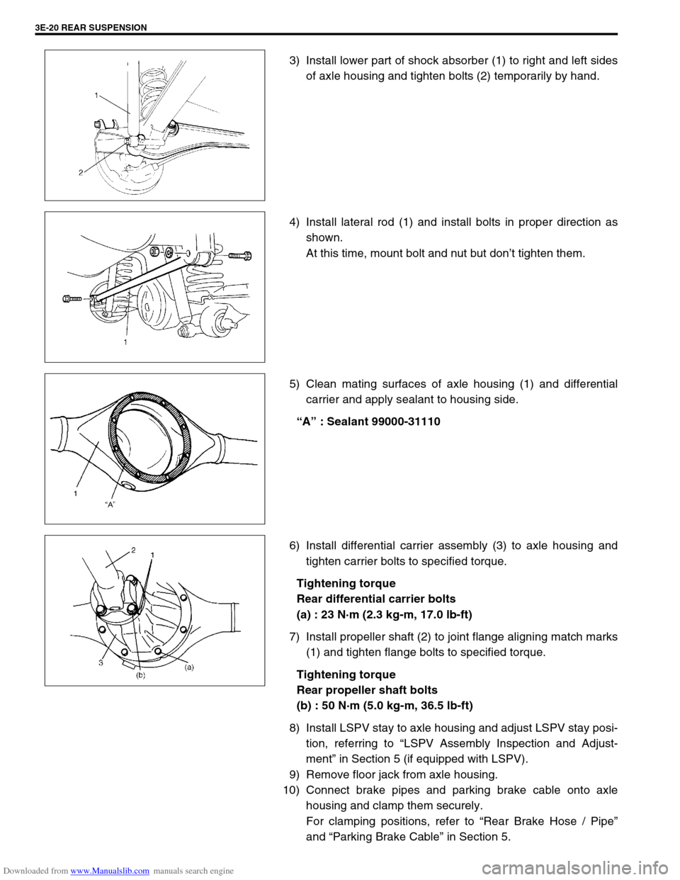
3) Install lower part of shock absorber (1) to right and left sides
of axle housing and tighten bolts (2) temporarily by hand.
4) Install lateral rod (1) and install bolts in proper direction as
shown.
At this time, mount bolt and nut but don’t tighten them.
5) Clean mating surfaces of axle housing (1) and differential
carrier and apply sealant to housing side.
“A” : Sealant 99000-31110
6) Install differential carrier assembly (3) to axle housing and
tighten carrier bolts to specified torque.
Tightening torque
Rear differential carrier bolts
(a) : 23 N·m (2.3 kg-m, 17.0 lb-ft)
7) Install propeller shaft (2) to joint flange aligning match marks
(1) and tighten flange bolts to specified torque.
Tightening torque
Rear propeller shaft bolts
(b) : 50 N·m (5.0 kg-m, 36.5 lb-ft)
8) Install LSPV stay to axle housing and adjust LSPV stay posi-
tion, referring to “LSPV Assembly Inspection and Adjust-
ment” in Section 5 (if equipped with LSPV).
9) Remove floor jack from axle housing.
10) Connect brake pipes and parking brake cable onto axle
housing and clamp them securely.
For clamping positions, refer to “Rear Brake Hose / Pipe”
and “Parking Brake Cable” in Section 5.
Page 241 of 687

Downloaded from www.Manualslib.com manuals search engine 3E-22 REAR SUSPENSION
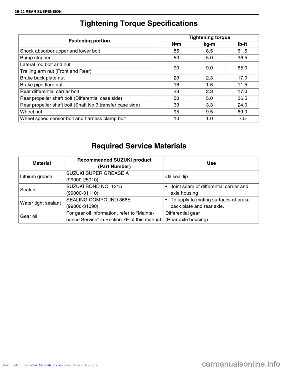
Tightening Torque Specifications
Required Service Materials
Fastening portionTightening torque
Nm kg-m lb-ft
Shock absorber upper and lower bolt 85 8.5 61.5
Bump stopper 50 5.0 36.5
Lateral rod bolt and nut
90 9.0 65.0
Trailing arm nut (Front and Rear)
Brake back plate nut 23 2.3 17.0
Brake pipe flare nut 16 1.6 11.5
Rear differential carrier bolt 23 2.3 17.0
Rear propeller shaft bolt (Differential case side) 50 5.0 36.5
Rear propeller shaft bolt (Shaft No.3 transfer case side) 33 3.3 24.0
Wheel nut 95 9.5 69.0
Wheel speed sensor bolt and harness clamp bolt 10 1.0 7.5
MaterialRecommended SUZUKI product
(Part Number)Use
Lithium greaseSUZUKI SUPER GREASE A
(99000-25010)Oil seal lip
SealantSUZUKI BOND NO. 1215
(99000-31110)Joint seam of differential carrier and
axle housing
Water tight sealantSEALING COMPOUND 366E
(99000-31090)To apply to mating surfaces of brake
back plate and rear axle.
Gear oilFor gear oil information, refer to “Mainte-
nance Service” in Section 7E of this manual.Differential gear
(Rear axle housing)
Page 248 of 687
Downloaded from www.Manualslib.com manuals search engine WHEELS AND TIRES 3F-5
WARNING:
Wheel spin should be limited to 35 mph (55 km/h) as indicated on speedometer.
This limit is necessary because speedometer only indicates one-half of actual wheel speed when one
drive wheel is spinning and the other drive wheel is stopped.
Unless care is taken in limiting drive wheel spin, spinning wheel can reach excessive speeds. This
can result in possible tire disintegration or differential failure, which could cause serious personal
injury or extensive vehicle damage.
CAUTION:
For vehicle equipped with ABS, using on-vehicle balancing method with ignition switch ON may set
malfunction diagnostic trouble code (DTC) of ABS even when system is in good condition.
Never turn ignition switch ON while spinning wheel.
Page 257 of 687

Downloaded from www.Manualslib.com manuals search engine 4B-4 PROPELLER SHAFTS
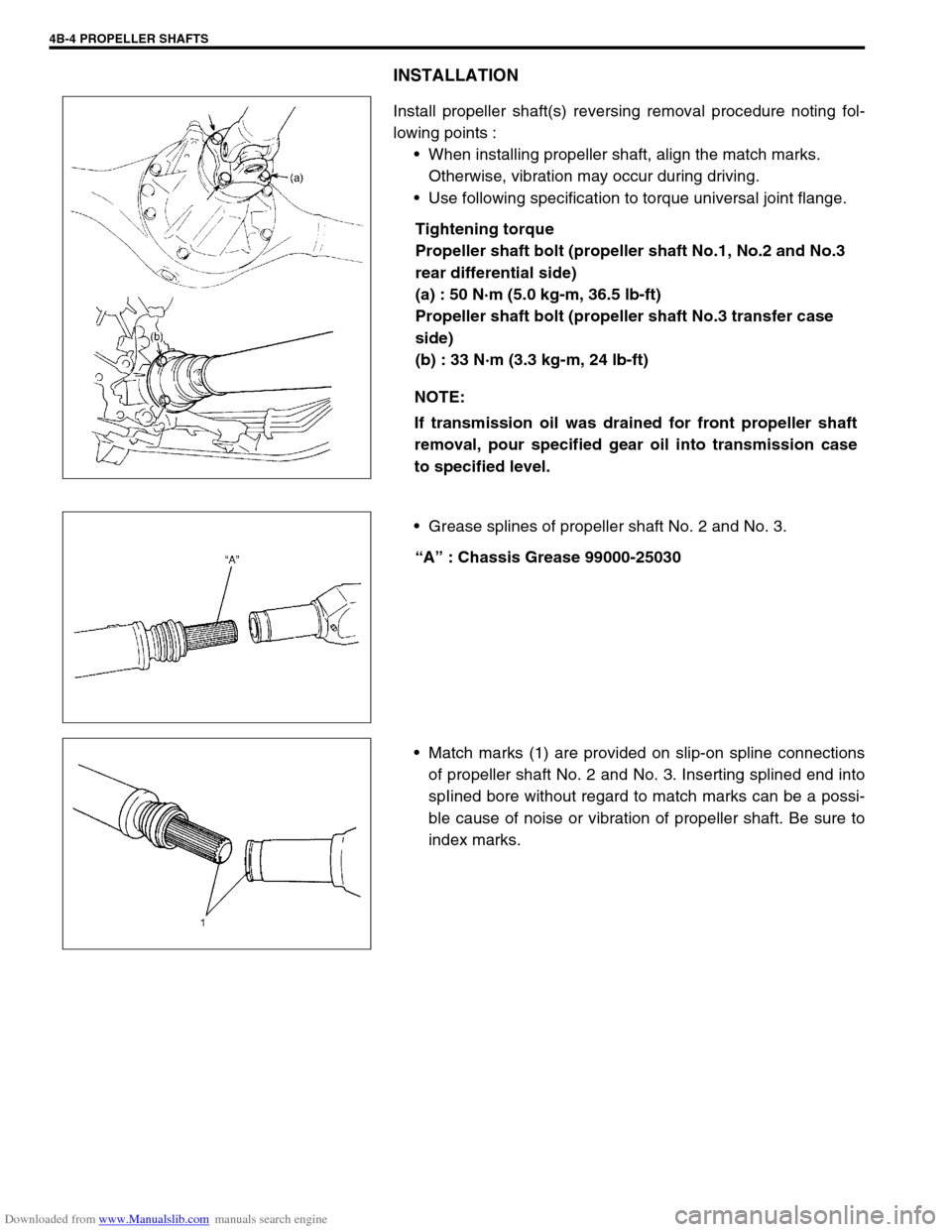
INSTALLATION
Install propeller shaft(s) reversing removal procedure noting fol-
lowing points :
When installing propeller shaft, align the match marks.
Otherwise, vibration may occur during driving.
Use following specification to torque universal joint flange.
Tightening torque
Propeller shaft bolt (propeller shaft No.1, No.2 and No.3
rear differential side)
(a) : 50 N·m (5.0 kg-m, 36.5 lb-ft)
Propeller shaft bolt (propeller shaft No.3 transfer case
side)
(b) : 33 N·m (3.3 kg-m, 24 lb-ft)
Grease splines of propeller shaft No. 2 and No. 3.
“A” : Chassis Grease 99000-25030
Match marks (1) are provided on slip-on spline connections
of propeller shaft No. 2 and No. 3. Inserting splined end into
spIined bore without regard to match marks can be a possi-
ble cause of noise or vibration of propeller shaft. Be sure to
index marks. NOTE:
If transmission oil was drained for front propeller shaft
removal, pour specified gear oil into transmission case
to specified level.
Page 268 of 687
Downloaded from www.Manualslib.com manuals search engine BRAKES 5-7
Brake warning light
turns on when brake
is appliedBrake fluid leaking from brake line Investigate leaky point, correct it
and add brake fluid.
Insufficient amount of brake fluid Add brake fluid.
Faulty P & Differential valve (Differential switch) Replace.
Brake warning light
fails to turn on even
when parking brake is
appliedBulb burnt out Replace bulb.
Brake warning light circuit open Repair circuit.
ABS warning light
does not turn on for 2
sec. after ignition
switch has turned ON.Bulb burnt out Replace bulb.
ABS warning light circuit open, if equipped with
ABS (including check relay)Check system referring to “TABLE-
A” in Section 5E.
ABS warning light
remains on after igni-
tion switch has turned
on for 2 sec.Malfunctioning ABS, if equipped with ABS Check system referring to “TABLE-
B” in Section 5E. Condition Possible Cause Correction
Page 295 of 687

Downloaded from www.Manualslib.com manuals search engine 5-34 BRAKES
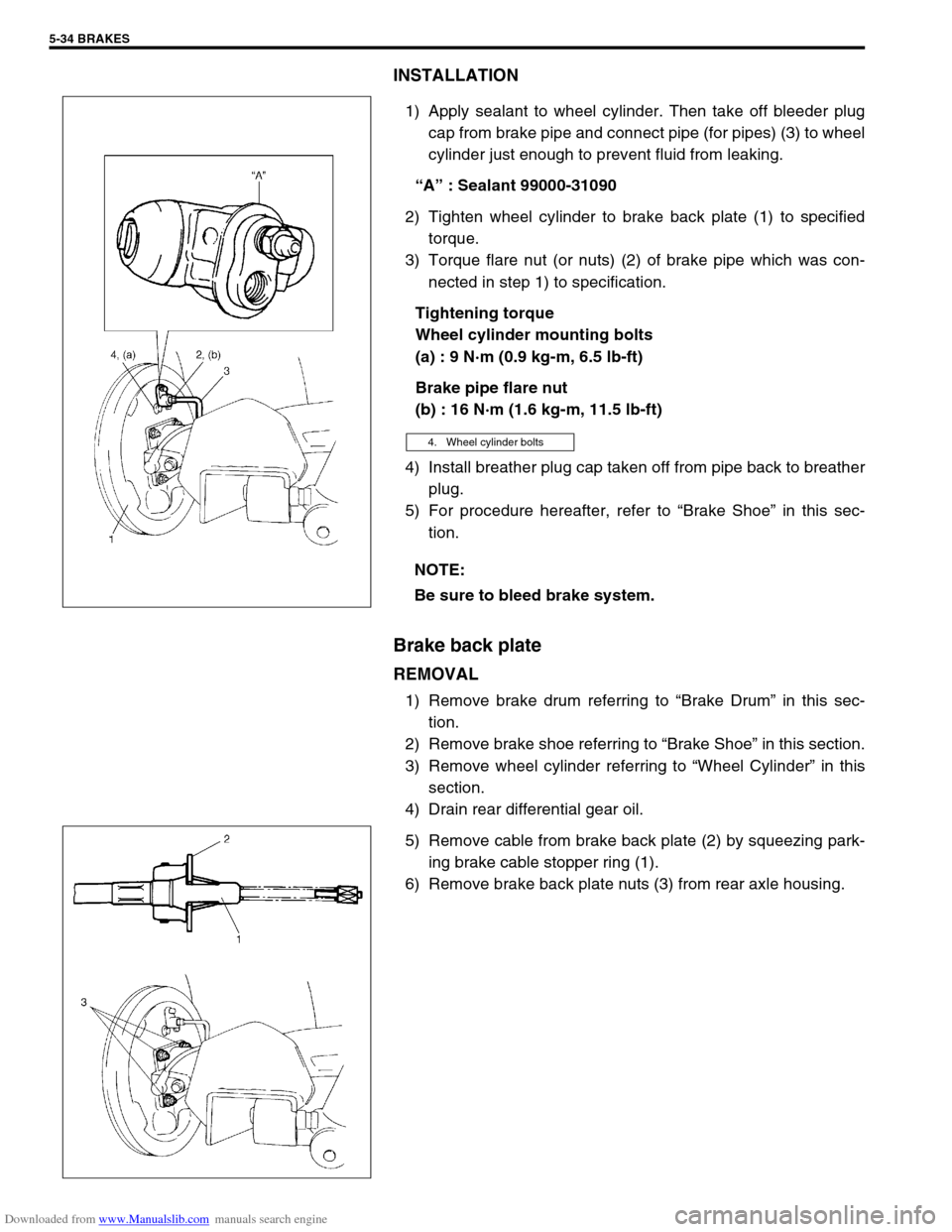
INSTALLATION
1) Apply sealant to wheel cylinder. Then take off bleeder plug
cap from brake pipe and connect pipe (for pipes) (3) to wheel
cylinder just enough to prevent fluid from leaking.
“A” : Sealant 99000-31090
2) Tighten wheel cylinder to brake back plate (1) to specified
torque.
3) Torque flare nut (or nuts) (2) of brake pipe which was con-
nected in step 1) to specification.
Tightening torque
Wheel cylinder mounting bolts
(a) : 9 N·m (0.9 kg-m, 6.5 lb-ft)
Brake pipe flare nut
(b) : 16 N·m (1.6 kg-m, 11.5 lb-ft)
4) Install breather plug cap taken off from pipe back to breather
plug.
5) For procedure hereafter, refer to “Brake Shoe” in this sec-
tion.
Brake back plate
REMOVAL
1) Remove brake drum referring to “Brake Drum” in this sec-
tion.
2) Remove brake shoe referring to “Brake Shoe” in this section.
3) Remove wheel cylinder referring to “Wheel Cylinder” in this
section.
4) Drain rear differential gear oil.
5) Remove cable from brake back plate (2) by squeezing park-
ing brake cable stopper ring (1).
6) Remove brake back plate nuts (3) from rear axle housing.
4. Wheel cylinder bolts
NOTE:
Be sure to bleed brake system.
Page:
< prev 1-8 9-16 17-24