Page 96 of 687
Downloaded from www.Manualslib.com manuals search engine AIR CONDITIONING (OPTIONAL) 1B-35
3) Drain engine coolant and disconnect heater hoses (1) from
heater unit.
4) Disable air bag system referring to “Disabling Air Bag Sys-
tem” in Section 10B (if equipped).
5) Remove attaching bolt (1).
6) Disconnect suction hose (2) and receiver / dryer outlet pipe
(3) from expansion valve (4).
7) Remove instrument panel referring to “Instrument Panel” in
Section 9.
8) Remove cooling unit (1) with heater unit (2) from vehicle
body.
9) Remove cooling unit (1) from heater unit (2).
INSPECTION
Check the following.
Check clog of A/C evaporator fins.
If any clogs are found, A/C evaporator fins should be
washed with water, and should be dried with compressed
air.
Check A/C evaporator fins for leakage and breakage.
If any defects are found, repair or replace A/C evaporator.
Check A/C evaporator fittings for leakage.
If any defects are found, repair or replace A/C evaporator.
Page 98 of 687
Downloaded from www.Manualslib.com manuals search engine AIR CONDITIONING (OPTIONAL) 1B-37
A/C Evaporator Thermistor (A/C Evaporator
Temperature Sensor)
INSPECTION
Check resistance between terminals for A/C evaporator ther-
mistor (1).
If check results are as not specified, replace thermistor.
A/C evaporator temperature sensor resistance
Expansion Valve
INSPECTION
Refer to “Performance Diagnosis” in this section.
REMOVAL
1) Disconnect negative (–) cable at battery.
2) Recover refrigerant from A/C system by referring to
“Recover” in this section.
3) Remove attaching bolt (1).
4) Remove suction hose (2) and receiver dryer outlet pipe (3)
from expansion valve (4).
5) Remove expansion valve (4).Sensor Temperature (°C (°F)) Resistance (k
Ω)
0 (32) 6.4 – 7.0
25 (77) 1.8 – 2.2
NOTE:
When A/C evaporator thermistor (1) removed, its should
be reinstalled in original position.
NOTE:
The amount of removed compressor oil must be mea-
sured for replenishing compressor oil.
Page 101 of 687

Downloaded from www.Manualslib.com manuals search engine 1B-40 AIR CONDITIONING (OPTIONAL)
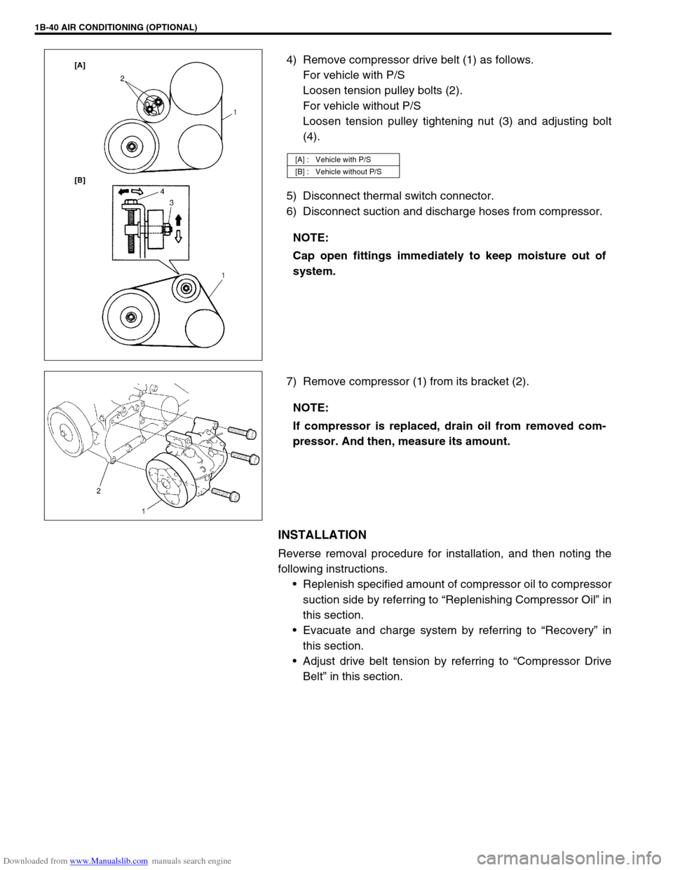
4) Remove compressor drive belt (1) as follows.
For vehicle with P/S
Loosen tension pulley bolts (2).
For vehicle without P/S
Loosen tension pulley tightening nut (3) and adjusting bolt
(4).
5) Disconnect thermal switch connector.
6) Disconnect suction and discharge hoses from compressor.
7) Remove compressor (1) from its bracket (2).
INSTALLATION
Reverse removal procedure for installation, and then noting the
following instructions.
Replenish specified amount of compressor oil to compressor
suction side by referring to “Replenishing Compressor Oil” in
this section.
Evacuate and charge system by referring to “Recovery” in
this section.
Adjust drive belt tension by referring to “Compressor Drive
Belt” in this section.
[A] : Vehicle with P/S
[B] : Vehicle without P/S
NOTE:
Cap open fittings immediately to keep moisture out of
system.
NOTE:
If compressor is replaced, drain oil from removed com-
pressor. And then, measure its amount.
Page 102 of 687
Downloaded from www.Manualslib.com manuals search engine AIR CONDITIONING (OPTIONAL) 1B-41
Magnet Clutch
1. Thermal switch 6. Magnet clutch coil a. Front head bolt
: Tighten bolt “a” first, and next “b”.
2. Compressor body assembly 7. Compressor pulley b. Front head bolt
: Tighten bolt “a” first, and next “b”.
3. O-ring 8. Circlip c. Clutch plate bolt
4. Lip seal 9. Shim Tightening torque
5. Front head 10. Clutch plate Do not reuse.
Page 103 of 687
Downloaded from www.Manualslib.com manuals search engine 1B-42 AIR CONDITIONING (OPTIONAL)
INSPECTION
Check clutch plate and clutch pulley for leaks of compressor
oil.
Check clutch bearing of compressor pulley for noise, wear
and grease leakage.
Measure resistance of magnet clutch coil (1) between mag-
net clutch lead wire (2) and compressor body assembly.
If measured resistance is not within tolerance, replace mag-
net clutch coil.
Magnet Clutch coil resistance
: 3.4 – 4.1
Ω at 20 °C (68 °F)
Check thermal switch (1) for continuity using ohmmeter.
If it is no continuity, replace thermal switch.
REMOVAL
1) Remove compressor from vehicle referring to “Compressor”
in this section.
2) Fix clutch plate (1) with special tool, and remove clutch plate
bolt (2) and washer (3).
Special tool
(A) : 09991-06020
3) Remove clutch plate (1) using special tool.
Special tool
(A) : 09991-06030
Page 105 of 687
Downloaded from www.Manualslib.com manuals search engine 1B-44 AIR CONDITIONING (OPTIONAL)
3) Install magnet clutch.
a) Set magnet clutch squarely over clutch installation boss.
b) Place special tool onto clutch bearing.
Ensure that edge rests only on inner race of bearing.
Special tool
(A) : 09991-06010
4) Install snap ring (1) using special tool.
Special tool
(A) : 09900-06107
5) Adjust clearance between clutch plate (1) and magnet clutch
coil (2) by putting shim on compressor shaft.
Standard clearance between clutch plate and magnet
clutch coil
“a” : 0.3 – 0.6 mm (0.012 – 0.024 in.)
6) Tighten new clutch plate bolt (1) as specified torque.
Tightening torque
Clutch plate bolt
(a) : 14 N·m (1.4 kg-m, 10.5 lb-ft)
Special tool
(A) : 09991-06020
CAUTION:
Be careful not to scratch bearing seal.
Page 106 of 687
Downloaded from www.Manualslib.com manuals search engine AIR CONDITIONING (OPTIONAL) 1B-45
Lip Type Seal
REMOVAL
1) Remove magnet clutch referring to “Magnet Clutch” in this
section.
2) Remove front head mounting bolts (10 pcs).
3) Remove front head (1) by pushing compressor shaft (2).
4) Remove O-ring (5).
5) Remove lip type seal from front head (1) using bearing
remover (2).
INSTALLATION
1) Press-fit lip type seal (1) into front head (2) using special
tool.
Special tool
(A) : 09991-06050
1. Front head
NOTE:
Be careful not to remove cylinder (3) from compressor
body assembly (4).
CAUTION:
Do not reuse lip seal (1) once removed from compressor.
Page 107 of 687

Downloaded from www.Manualslib.com manuals search engine 1B-46 AIR CONDITIONING (OPTIONAL)
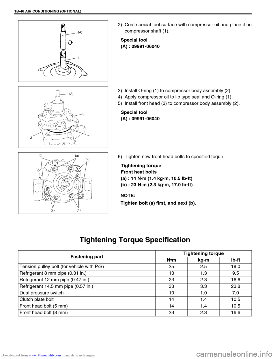
2) Coat special tool surface with compressor oil and place it on
compressor shaft (1).
Special tool
(A) : 09991-06040
3) Install O-ring (1) to compressor body assembly (2).
4) Apply compressor oil to lip type seal and O-ring (1).
5) Install front head (3) to compressor body assembly (2).
Special tool
(A) : 09991-06040
6) Tighten new front head bolts to specified toque.
Tightening torque
Front heat bolts
(a) : 14 N·m (1.4 kg-m, 10.5 lb-ft)
(b) : 23 N·m (2.3 kg-m, 17.0 lb-ft)
Tightening Torque Specification
NOTE:
Tighten bolt (a) first, and next (b).
Fastening partTightening torque
Nm kg-m lb-ft
Tension pulley bolt (for vehicle with P/S) 25 2.5 18.0
Refrigerant 8 mm pipe (0.31 in.) 13 1.3 9.5
Refrigerant 12 mm pipe (0.47 in.) 23 2.3 16.6
Refrigerant 14.5 mm pipe (0.57 in.) 33 3.3 23.8
Dual pressure switch 10 1.0 7.0
Clutch plate bolt 14 1.4 10.5
Front head bolt (5 mm) 14 1.4 10.5
Front head bolt (8 mm) 23 2.3 16.6