Page 295 of 687

Downloaded from www.Manualslib.com manuals search engine 5-34 BRAKES
INSTALLATION
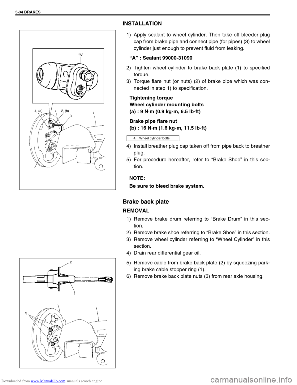
1) Apply sealant to wheel cylinder. Then take off bleeder plug
cap from brake pipe and connect pipe (for pipes) (3) to wheel
cylinder just enough to prevent fluid from leaking.
“A” : Sealant 99000-31090
2) Tighten wheel cylinder to brake back plate (1) to specified
torque.
3) Torque flare nut (or nuts) (2) of brake pipe which was con-
nected in step 1) to specification.
Tightening torque
Wheel cylinder mounting bolts
(a) : 9 N·m (0.9 kg-m, 6.5 lb-ft)
Brake pipe flare nut
(b) : 16 N·m (1.6 kg-m, 11.5 lb-ft)
4) Install breather plug cap taken off from pipe back to breather
plug.
5) For procedure hereafter, refer to “Brake Shoe” in this sec-
tion.
Brake back plate
REMOVAL
1) Remove brake drum referring to “Brake Drum” in this sec-
tion.
2) Remove brake shoe referring to “Brake Shoe” in this section.
3) Remove wheel cylinder referring to “Wheel Cylinder” in this
section.
4) Drain rear differential gear oil.
5) Remove cable from brake back plate (2) by squeezing park-
ing brake cable stopper ring (1).
6) Remove brake back plate nuts (3) from rear axle housing.
4. Wheel cylinder bolts
NOTE:
Be sure to bleed brake system.
Page 299 of 687

Downloaded from www.Manualslib.com manuals search engine 5-38 BRAKES
INSTALLATION
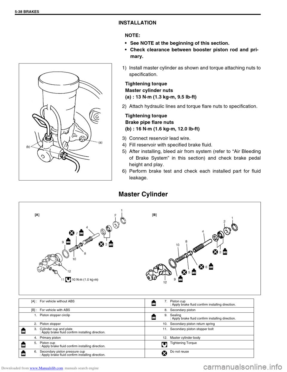
1) Install master cylinder as shown and torque attaching nuts to
specification.
Tightening torque
Master cylinder nuts
(a) : 13 N·m (1.3 kg-m, 9.5 Ib-ft)
2) Attach hydraulic lines and torque flare nuts to specification.
Tightening torque
Brake pipe flare nuts
(b) : 16 N·m (1.6 kg-m, 12.0 lb-ft)
3) Connect reservoir lead wire.
4) Fill reservoir with specified brake fluid.
5) After installing, bleed air from system (refer to “Air Bleeding
of Brake System” in this section) and check brake pedal
height and play.
6) Perform brake test and check each installed part for fluid
leakage.
Master Cylinder
NOTE:
See NOTE at the beginning of this section.
Check clearance between booster piston rod and pri-
mary.
[A] : For vehicle without ABS 7. Piston cup
: Apply brake fluid confirm installing direction.
[B] : For vehicle with ABS 8. Secondary piston
1. Piston stopper circlip 9. Sealing
: Apply brake fluid confirm installing direction.
2. Piston stopper 10. Secondary piston return spring
3. Cylinder cup and plate
: Apply brake fluid confirm installing direction.11. Secondary piston stopper bolt
4. Primary piston 12. Master cylinder body
5. Piston cup
: Apply brake fluid confirm installing direction.Tightening Torque
6. Secondary piston pressure cup
: Apply brake fluid confirm installing direction.Do not reuse
Page 303 of 687

Downloaded from www.Manualslib.com manuals search engine 5-42 BRAKES
LSPV (Load Sensing Proportioning Valve) Assembly (If Equipped)
REMOVAL
1) Clean around reservoir cap and take out fluid with syringe or
such.
2) Hoist vehicle.
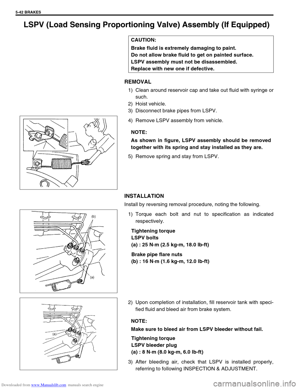
3) Disconnect brake pipes from LSPV.
4) Remove LSPV assembly from vehicle.
5) Remove spring and stay from LSPV.
INSTALLATION
Install by reversing removal procedure, noting the following.
1) Torque each bolt and nut to specification as indicated
respectively.
Tightening torque
LSPV bolts
(a) : 25 N·m (2.5 kg-m, 18.0 lb-ft)
Brake pipe flare nuts
(b) : 16 N·m (1.6 kg-m, 12.0 lb-ft)
2) Upon completion of installation, fill reservoir tank with speci-
fied fluid and bleed air from brake system.
Tightening torque
LSPV bleeder plug
(a) : 8 N·m (8.0 kg-m, 6.0 lb-ft)
3) After bleeding air, check that LSPV is installed properly,
referring to following INSPECTION & ADJUSTMENT. CAUTION:
Brake fluid is extremely damaging to paint.
Do not allow brake fluid to get on painted surface.
LSPV assembly must not be disassembled.
Replace with new one if defective.
NOTE:
As shown in figure, LSPV assembly should be removed
together with its spring and stay installed as they are.
NOTE:
Make sure to bleed air from LSPV bleeder without fail.
Page 305 of 687
Downloaded from www.Manualslib.com manuals search engine 5-44 BRAKES
P (Proportioning) Valve
REMOVAL
1) Clean around reservoir cap and take out fluid with syringe or
such.
2) Disconnect brake pipes from P valve.
3) Remove P valve.
INSTALLATION
1) Install P valve (2).
Tightening torque
P valve bolts
(a) : 25 N·m (2.5 kg-m, 18.0 lb-ft)
2) Tighten flare nuts to specified torque.
Tightening torque
Brake pipe flare nuts
(b) : 16 N·m (1.6 kg-m, 12.0 lb-ft)
3) Fill reservoir with specified brake fluid.
4) Bleed air from system.CAUTION:
Do not allow brake fluid to get on painted surfaces.
WARNING:
Never disassemble P valve assembly. If it is found faulty,
replace it with new assembly.
1. Flare nuts
Page 311 of 687
Downloaded from www.Manualslib.com manuals search engine 5-50 BRAKES
REMOVAL
1) Raise, suitably support vehicle. Remove wheel if necessary.
2) Clean dirt and foreign material from both hose end or pipe end fittings. Remove brake hose and pipe.
INSTALLATION
1) Install brake hose and pipe by reversing removal procedure, noting the following points.
For installation, make sure that steering wheel is in straightforward position and hose has no twist or kink.
Check to make sure that hose doesn’t contact any part of suspension, both in extreme right and extreme left
turn conditions. If it does at any point, remove and correct. Fill and maintain brake fluid level in reservoir.
Bleed brake system.
2) Perform brake test and check installed part for fluid leakage.
Page 312 of 687

Downloaded from www.Manualslib.com manuals search engine BRAKES 5-51
Rear Brake Hose/Pipe
REMOVAL
1) Raise, suitably support vehicle. Remove wheel if necessary.
2) Clean dirt and foreign material from both hose end or pipe end fittings. Remove brake hose and pipe.
INSTALLATION
1) Install brake hose and pipe by reversing removal procedure, noting the following points.
Fill and maintain brake fluid level in reservoir. Bleed brake system.
2) Perform brake test and check each installed part for fluid leakage.
CAUTION:
Position clamps to white marks on two brake pipes.
Be sure to obtain more than 3 mm (0.118 in.) clearance between axle housing and brake pipe.
Install clamps properly referring to figure below and tighten bolts.
When installing hose, make sure that it has no twist or kink.
T : Top side 2. Rear axle housing 5. Fuel tank 8. Brake pipe (vehicle with LSPV)
R : Right side 3. Rear wheel cylinder 6. Chassis frame a-b: Clamp
1. Clamp 4. LSPV (if equipped) 7. Fuel pipe Tightening torque
Page 315 of 687

Downloaded from www.Manualslib.com manuals search engine 5-54 BRAKES
Tightening Torque Specifications
Required Service Material
Fastening partTightening torque
Nm kg-m lb-ft
Brake caliper carrier bolt 85 8.5 61.5
Brake caliper pin bolt 22 2.2 16.0
Front brake flexible hose bolt 23 2.3 17.0
Rear brake back plate nut 23 2.3 17.0
Master cylinder nut 13 1.3 9.5
Booster nut 13 1.3 9.5
Brake pipe 5-way 4-way joint bolt 11 1.1 8.0
Brake pipe flare nut 16 1.6 12.0
LSPV bolt/P valve bolt 25 2.5 18.0
Brake bleeder plugFront caliper 11 1.1 8.0
Rear wheel cylinder, LSPV 8 0.8 6.0
Wheel nut 95 9.5 69.0
Hose bracket bolt 11 1.1 8.0
Booster clevis nut 25 2.5 18.0
Stop light switch lock nut 6.5 0.65 4.7
Parking brake lever bolt 23 2.3 17.0
Wheel cylinder mounting bolt 9 0.9 6.5
Piston stopper bolt 10 1.0 7.5
LSPV adjust bolt 25 2.5 18.0
Material Recommended SUZUKI products Use
Brake fluid Indicated on reservoir tank cap or
described in owner’s manual of vehi-
cleTo fill master cylinder reservoir.
To clean and apply to inner parts of master
cylinder caliper and wheel cylinder when they
are disassembled.
Water tight sealant SEALING COMPOUND 366E
99000-31090To apply to mating surfaces of brake back
plate and rear wheel cylinder.
Sealant SUZUKI BOND NO. 1215
99000-31110To apply to mating surfaces of brake back
plate and rear axle housing.
To apply to mating surfaces of brake back
plate and rear wheel bearing retainer.
Page 347 of 687
Downloaded from www.Manualslib.com manuals search engine 5E-30 ANTILOCK BRAKE SYSTEM (ABS)
ABS Hydraulic Unit / Control Module Assembly
HYDRAULIC UNIT INSPECTION
Check hydraulic unit for fluid leakage.
If any, repair or replace.
REMOVAL
1) Disconnect negative cable at battery.
2) Using special tool, disconnect brake pipes from ABS hydrau-
lic unit / control module assembly (1).
Special tool
(A) : 09950-78220 CAUTION:
Do not disassemble ABS hydraulic unit / control module assembly, loosen blind plug or remove
motor. Performing any of these prohibited services will affect original performance of ABS hydraulic
unit / control module assembly.
1. Brake pipe 3. Bracket Tightening torque
2. ABS hydraulic unit / control module assembly 4. Connector
NOTE:
Put bleeder plug cap onto pipe to prevent fluid from spill-
ing. Do not allow brake fluid to get on painted surfaces.