Page 270 of 687
Downloaded from www.Manualslib.com manuals search engine BRAKES 5-9
Excessive Pedal Travel Check
1) Start engine.
2) Depress brake pedal a few times.
3) With brake pedal depressed with approximately 30 kg (66
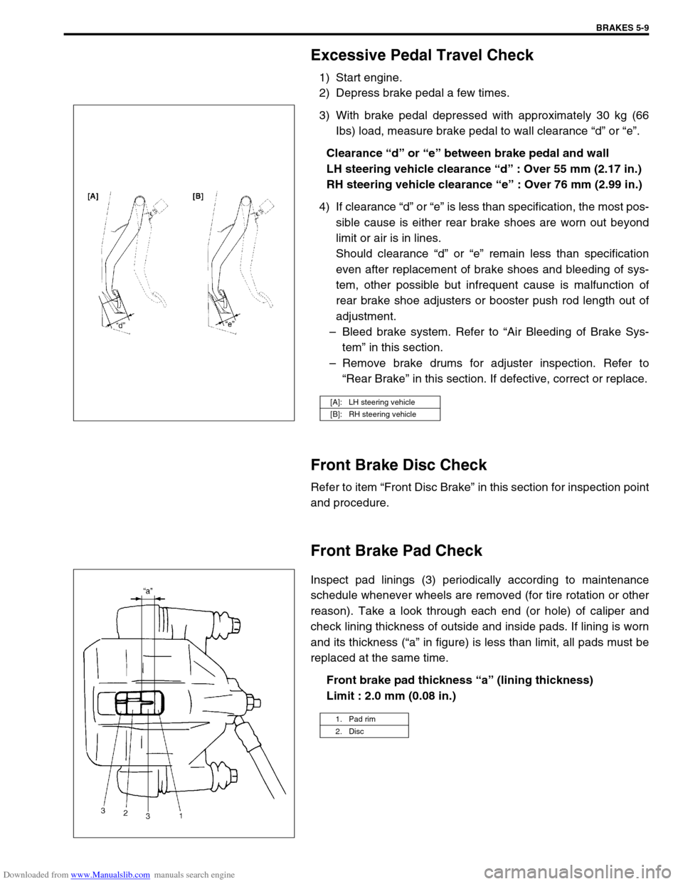
Ibs) load, measure brake pedal to wall clearance “d” or “e”.
Clearance “d” or “e” between brake pedal and wall
LH steering vehicle clearance “d” : Over 55 mm (2.17 in.)
RH steering vehicle clearance “e” : Over 76 mm (2.99 in.)
4) If clearance “d” or “e” is less than specification, the most pos-
sible cause is either rear brake shoes are worn out beyond
limit or air is in lines.
Should clearance “d” or “e” remain less than specification
even after replacement of brake shoes and bleeding of sys-
tem, other possible but infrequent cause is malfunction of
rear brake shoe adjusters or booster push rod length out of
adjustment.
–Bleed brake system. Refer to “Air Bleeding of Brake Sys-
tem” in this section.
–Remove brake drums for adjuster inspection. Refer to
“Rear Brake” in this section. If defective, correct or replace.
Front Brake Disc Check
Refer to item “Front Disc Brake” in this section for inspection point
and procedure.
Front Brake Pad Check
Inspect pad linings (3) periodically according to maintenance
schedule whenever wheels are removed (for tire rotation or other
reason). Take a look through each end (or hole) of caliper and
check lining thickness of outside and inside pads. If lining is worn
and its thickness (“a” in figure) is less than limit, all pads must be
replaced at the same time.
Front brake pad thickness “a” (lining thickness)
Limit : 2.0 mm (0.08 in.)
[A]: LH steering vehicle
[B]: RH steering vehicle
1. Pad rim
2. Disc
Page 276 of 687
Downloaded from www.Manualslib.com manuals search engine BRAKES 5-15
Fluid Pressure Test (If Equipped with LSPV)
Test procedure for LSPV assembly is as follows.
Before testing, confirm the following.
Fuel tank is filled with fuel fully.
Vehicle is equipped with spare tire, tools, jack and jack han-
dle.
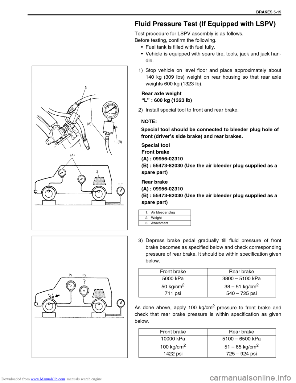
1) Stop vehicle on level floor and place approximately about
140 kg (309 Ibs) weight on rear housing so that rear axle
weights 600 kg (1323 Ib).
Rear axle weight
“L” : 600 kg (1323 lb)
2) Install special tool to front and rear brake.
Special tool
Front brake
(A) : 09956-02310
(B) : 55473-82030 (Use the air bleeder plug supplied as a
spare part)
Rear brake
(A) : 09956-02310
(B) : 55473-82030 (Use the air bleeder plug supplied as a
spare part)
3) Depress brake pedal gradually till fluid pressure of front
brake becomes as specified below and check corresponding
pressure of rear brake. It should be within specification given
below.
As done above, apply 100 kg/cm
2 pressure to front brake and
check that rear brake pressure is within specification as given
below.NOTE:
Special tool should be connected to bleeder plug hole of
front (driver’s side brake) and rear brakes.
1. Air bleeder plug
2. Weight
3. Attachment
Front brake Rear brake
5000 kPa
50 kg/cm
2
711 psi3800 – 5100 kPa
38 – 51 kg/cm
2
540 – 725 psi
Front brake Rear brake
10000 kPa
100 kg/cm
2
1422 psi5100 – 6500 kPa
51 – 65 kg/cm
2
725 – 924 psi
Page 278 of 687
Downloaded from www.Manualslib.com manuals search engine BRAKES 5-17
On-Vehicle Service
Air Bleeding of Brake System
Bleeding operation is necessary to remove air whenever it
entered hydraulic brake system.
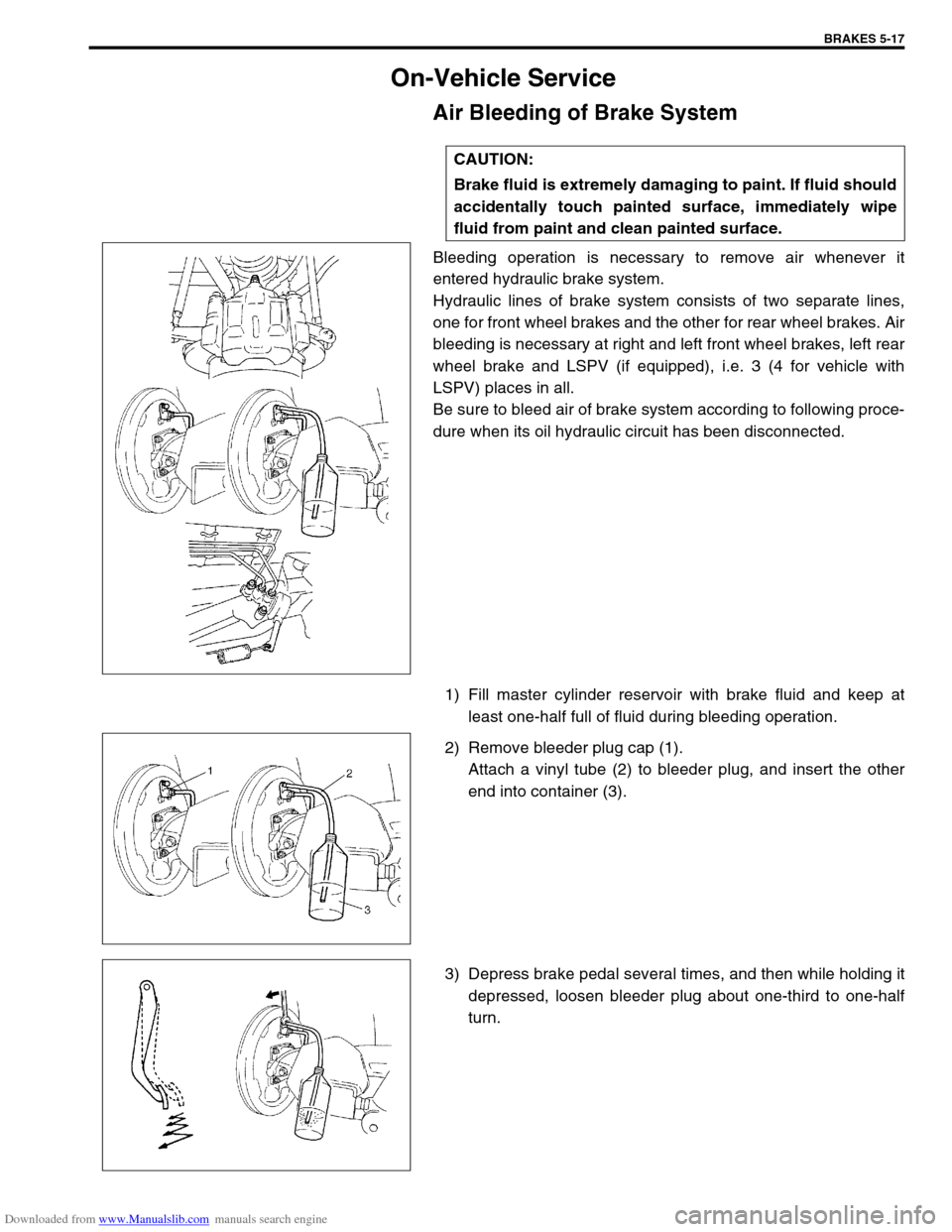
Hydraulic lines of brake system consists of two separate lines,
one for front wheel brakes and the other for rear wheel brakes. Air
bleeding is necessary at right and left front wheel brakes, left rear
wheel brake and LSPV (if equipped), i.e. 3 (4 for vehicle with
LSPV) places in all.
Be sure to bleed air of brake system according to following proce-
dure when its oil hydraulic circuit has been disconnected.
1) Fill master cylinder reservoir with brake fluid and keep at
least one-half full of fluid during bleeding operation.
2) Remove bleeder plug cap (1).
Attach a vinyl tube (2) to bleeder plug, and insert the other
end into container (3).
3) Depress brake pedal several times, and then while holding it
depressed, loosen bleeder plug about one-third to one-half
turn. CAUTION:
Brake fluid is extremely damaging to paint. If fluid should
accidentally touch painted surface, immediately wipe
fluid from paint and clean painted surface.
Page 279 of 687
Downloaded from www.Manualslib.com manuals search engine 5-18 BRAKES
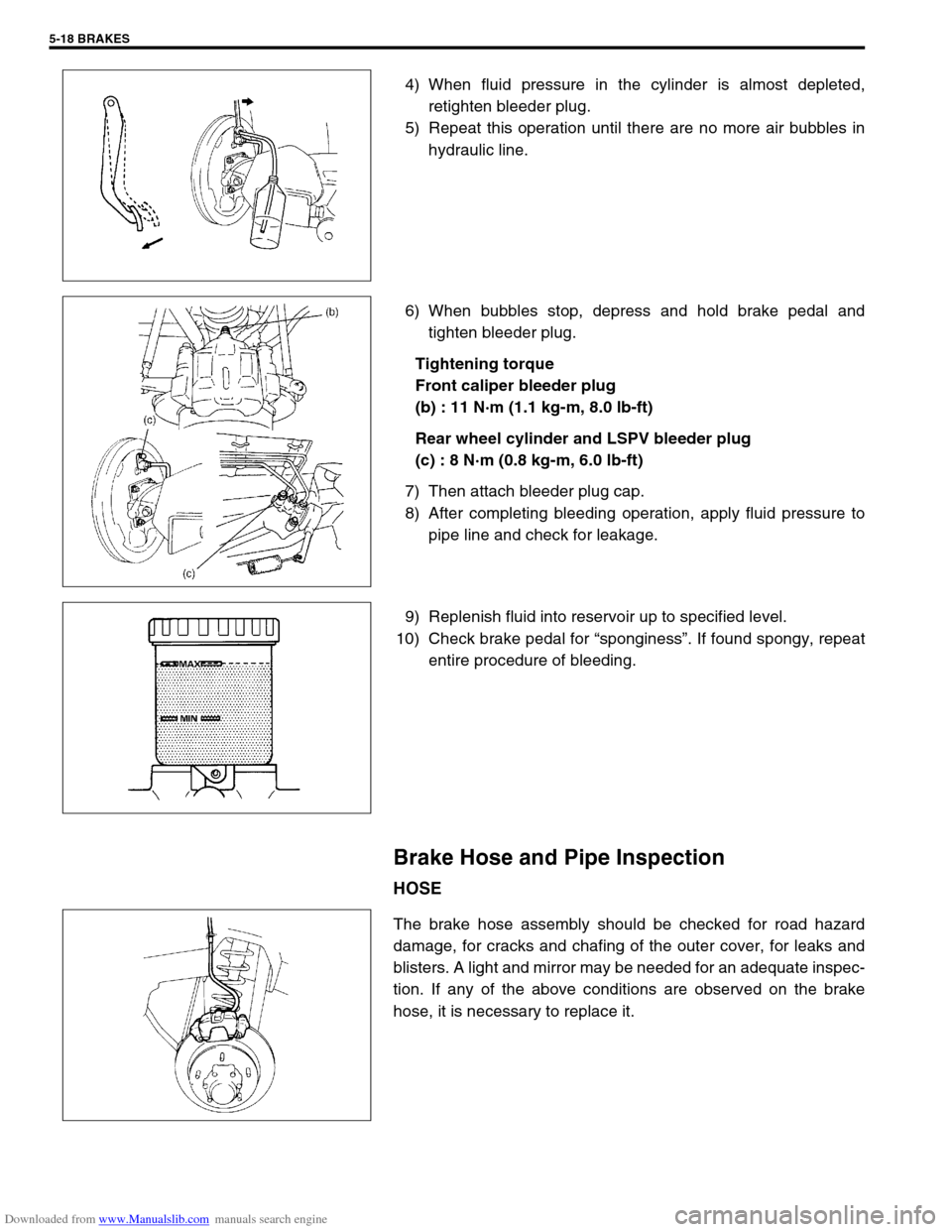
4) When fluid pressure in the cylinder is almost depleted,
retighten bleeder plug.
5) Repeat this operation until there are no more air bubbles in
hydraulic line.
6) When bubbles stop, depress and hold brake pedal and
tighten bleeder plug.
Tightening torque
Front caliper bleeder plug
(b) : 11 N·m (1.1 kg-m, 8.0 lb-ft)
Rear wheel cylinder and LSPV bleeder plug
(c) : 8 N·m (0.8 kg-m, 6.0 lb-ft)
7) Then attach bleeder plug cap.
8) After completing bleeding operation, apply fluid pressure to
pipe line and check for leakage.
9) Replenish fluid into reservoir up to specified level.
10) Check brake pedal for “sponginess”. If found spongy, repeat
entire procedure of bleeding.
Brake Hose and Pipe Inspection
HOSE
The brake hose assembly should be checked for road hazard
damage, for cracks and chafing of the outer cover, for leaks and
blisters. A light and mirror may be needed for an adequate inspec-
tion. If any of the above conditions are observed on the brake
hose, it is necessary to replace it.
Page 280 of 687
Downloaded from www.Manualslib.com manuals search engine BRAKES 5-19
PIPE
Inspect the tube for damage, cracks, dents and corrosion. If any
defect is found, replace it.
Front Disc Brake
1. Caliper pin bolt 10. Carrier bolt
2. Boot11. Brake caliper carrier
3. Cylinder slide bush
: Apply rubber grease to mating surface of caliper12. Pad clip
4. Bleeder plug cap 13. Disc brake caliper
5. Bleeder plug 14. Disc brake pad
6. Anti noise shim 15. Piston seal
: Apply brake fluid to all around part of piston seal
7. Disc brake piston
: Apply brake fluid to contact surface of cylinderTightening torque
8. Cylinder bootDo not reuse.
9. Seat ring (boot ring)
Page 283 of 687
Downloaded from www.Manualslib.com manuals search engine 5-22 BRAKES
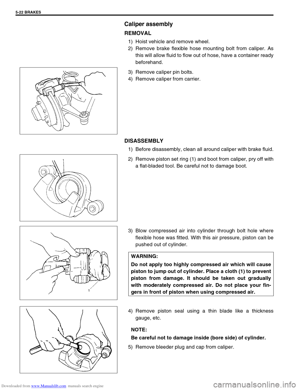
Caliper assembly
REMOVAL
1) Hoist vehicle and remove wheel.
2) Remove brake flexible hose mounting bolt from caliper. As
this will allow fluid to flow out of hose, have a container ready
beforehand.
3) Remove caliper pin bolts.
4) Remove caliper from carrier.
DISASSEMBLY
1) Before disassembly, clean all around caliper with brake fluid.
2) Remove piston set ring (1) and boot from caliper, pry off with
a flat-bladed tool. Be careful not to damage boot.
3) Blow compressed air into cylinder through bolt hole where
flexible hose was fitted. With this air pressure, piston can be
pushed out of cylinder.
4) Remove piston seal using a thin blade like a thickness
gauge, etc.
5) Remove bleeder plug and cap from caliper.
WARNING:
Do not apply too highly compressed air which will cause
piston to jump out of cylinder. Place a cloth (1) to prevent
piston from damage. It should be taken out gradually
with moderately compressed air. Do not place your fin-
gers in front of piston when using compressed air.
NOTE:
Be careful not to damage inside (bore side) of cylinder.
Page 285 of 687

Downloaded from www.Manualslib.com manuals search engine 5-24 BRAKES
ASSEMBLY
1) Check that slide bushes and boots for wear, corrosion, dam-
age, movement or deterioration. If it is found faulty, correct or
replace.
Apply rubber grease to bush outer surface. And then make
sure that each bush slides easily through each caliper bolt
hole.
2) Tighten bleeder plug to specified torque and install cap.
Tightening torque
Front caliper bleeder plug
(a) : 11 N·m (1.1 g-m, 8.0 lb-ft)
3) Piston seal is used to seal piston and cylinder and to adjust
clearance between pad and disc. Replace with a new one at
every overhaul. Fit piston seal into groove in cylinder taking
care not to twist it.
4) Before inserting piston (2) into cylinder, install new boot (1)
onto piston (2) as shown.
“A” : 2-grooved side directed inside
“B” : 3-grooved side directed outside CAUTION:
Wash each part cleanly before installation in the same
fluid as the one used in master cylinder reservoir.
Never use other fluid or thinner.
Before installing piston and piston seal to cylinder,
apply fluid to them.
After reassembling brake lines, bleed air from them.
NOTE:
Where temperature gets as low as – 30 °C (– 22 °F) in cold
weather, use rubber grease whose viscosity varies very
little even at – 40 °C (– 40 °F).
1. Apply rubber grease
Page 287 of 687
Downloaded from www.Manualslib.com manuals search engine 5-26 BRAKES
3) Install brake flexible hose (4) as shown and torque hose
mounting bolt (3) to specification.
Tightening torque
Front brake flexible hose bolt
(a) : 23 N·m (2.3 kg-m, 17.0 lb-ft)
4) Install wheel and torque wheel nuts to specification.
5) After completing installation, fill reservoir with brake fluid and
bleed brake system. Perform brake test and check each
installed part for oil leakage.
Brake Disc
REMOVAL
1) Hoist vehicle and remove wheel.
2) Remove caliper assembly by loosening carrier bolts (2 pcs).
3) Pull brake disc off by using 8 mm bolts (1) (2 pcs).
1. Brake caliper
2. Washer
CAUTION:
During removal, be careful not to damage brake flexible
hose and not to depress brake pedal.