2005 SUZUKI JIMNY Brake line
[x] Cancel search: Brake linePage 285 of 687

Downloaded from www.Manualslib.com manuals search engine 5-24 BRAKES
ASSEMBLY
1) Check that slide bushes and boots for wear, corrosion, dam-
age, movement or deterioration. If it is found faulty, correct or
replace.
Apply rubber grease to bush outer surface. And then make
sure that each bush slides easily through each caliper bolt
hole.
2) Tighten bleeder plug to specified torque and install cap.
Tightening torque
Front caliper bleeder plug
(a) : 11 N·m (1.1 g-m, 8.0 lb-ft)
3) Piston seal is used to seal piston and cylinder and to adjust
clearance between pad and disc. Replace with a new one at
every overhaul. Fit piston seal into groove in cylinder taking
care not to twist it.
4) Before inserting piston (2) into cylinder, install new boot (1)
onto piston (2) as shown.
“A” : 2-grooved side directed inside
“B” : 3-grooved side directed outside CAUTION:
Wash each part cleanly before installation in the same
fluid as the one used in master cylinder reservoir.
Never use other fluid or thinner.
Before installing piston and piston seal to cylinder,
apply fluid to them.
After reassembling brake lines, bleed air from them.
NOTE:
Where temperature gets as low as – 30 °C (– 22 °F) in cold
weather, use rubber grease whose viscosity varies very
little even at – 40 °C (– 40 °F).
1. Apply rubber grease
Page 291 of 687

Downloaded from www.Manualslib.com manuals search engine 5-30 BRAKES
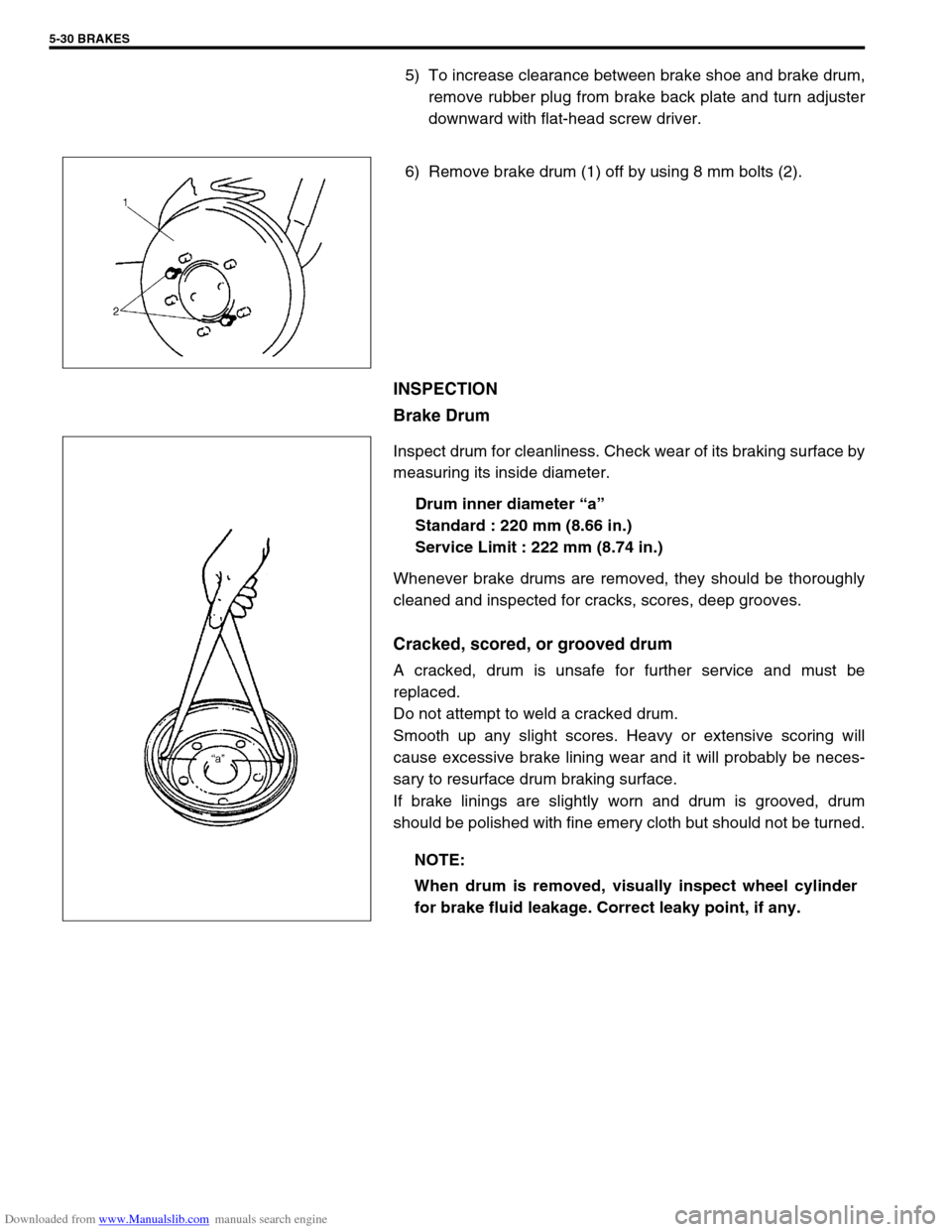
5) To increase clearance between brake shoe and brake drum,
remove rubber plug from brake back plate and turn adjuster
downward with flat-head screw driver.
6) Remove brake drum (1) off by using 8 mm bolts (2).
INSPECTION
Brake Drum
Inspect drum for cleanliness. Check wear of its braking surface by
measuring its inside diameter.
Drum inner diameter “a”
Standard : 220 mm (8.66 in.)
Service Limit : 222 mm (8.74 in.)
Whenever brake drums are removed, they should be thoroughly
cleaned and inspected for cracks, scores, deep grooves.
Cracked, scored, or grooved drum
A cracked, drum is unsafe for further service and must be
replaced.
Do not attempt to weld a cracked drum.
Smooth up any slight scores. Heavy or extensive scoring will
cause excessive brake lining wear and it will probably be neces-
sary to resurface drum braking surface.
If brake linings are slightly worn and drum is grooved, drum
should be polished with fine emery cloth but should not be turned.
NOTE:
When drum is removed, visually inspect wheel cylinder
for brake fluid leakage. Correct leaky point, if any.
Page 299 of 687

Downloaded from www.Manualslib.com manuals search engine 5-38 BRAKES
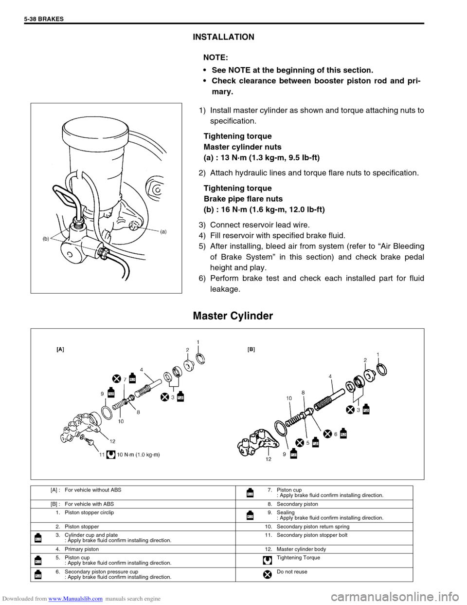
INSTALLATION
1) Install master cylinder as shown and torque attaching nuts to
specification.
Tightening torque
Master cylinder nuts
(a) : 13 N·m (1.3 kg-m, 9.5 Ib-ft)
2) Attach hydraulic lines and torque flare nuts to specification.
Tightening torque
Brake pipe flare nuts
(b) : 16 N·m (1.6 kg-m, 12.0 lb-ft)
3) Connect reservoir lead wire.
4) Fill reservoir with specified brake fluid.
5) After installing, bleed air from system (refer to “Air Bleeding
of Brake System” in this section) and check brake pedal
height and play.
6) Perform brake test and check each installed part for fluid
leakage.
Master Cylinder
NOTE:
See NOTE at the beginning of this section.
Check clearance between booster piston rod and pri-
mary.
[A] : For vehicle without ABS 7. Piston cup
: Apply brake fluid confirm installing direction.
[B] : For vehicle with ABS 8. Secondary piston
1. Piston stopper circlip 9. Sealing
: Apply brake fluid confirm installing direction.
2. Piston stopper 10. Secondary piston return spring
3. Cylinder cup and plate
: Apply brake fluid confirm installing direction.11. Secondary piston stopper bolt
4. Primary piston 12. Master cylinder body
5. Piston cup
: Apply brake fluid confirm installing direction.Tightening Torque
6. Secondary piston pressure cup
: Apply brake fluid confirm installing direction.Do not reuse
Page 302 of 687

Downloaded from www.Manualslib.com manuals search engine BRAKES 5-41
Fluid to fill reservoir with is indicated on reservoir cap of that vehi-
cle with embossed letters or in owner’s manual supplied with it.
Add fluid up to MAX line.
Page 362 of 687

Downloaded from www.Manualslib.com manuals search engine ENGINE GENERAL INFORMATION AND DIAGNOSIS 6-5
Fuel pressure relief procedure
After making sure that engine is cold, release fuel pressure as fol-
lows.
1) Place transmission gear shift lever in “Neutral” (Shift selector
lever to “P” range for A/T model), set parking brake, and
block drive wheels.
2) Remove relay box cover.
3) Disconnect fuel pump relay (1) from its connector.
4) Remove fuel filler cap to release fuel vapor pressure in fuel
tank and then reinstall it.
5) Start engine and run it till it stops for lack of fuel. Repeat
cranking engine 2-3 times for about 3 seconds each time to
dissipate fuel pressure in lines. Fuel connections are now
safe for servicing.
6) Upon completion of servicing, connect fuel pump relay (1) to
its connector.
Fuel leakage check procedure
After performing any service on fuel system, check to make sure
that there are no fuel leakages as follows.
1) Turn ON ignition switch for 3 seconds (to operate fuel pump)
and then turn it OFF.
Repeat this (ON and OFF) 3 or 4 times and apply fuel pres-
sure to fuel line. (till fuel pressure is felt by hand placed on
fuel feed hose.)
2) In this state, check to see that there are no fuel leakages
from any part of fuel system. CAUTION:
This work must not be done when engine is hot. If done
so, it may cause adverse effect to catalyst.
Page 381 of 687

Downloaded from www.Manualslib.com manuals search engine 6-24 ENGINE GENERAL INFORMATION AND DIAGNOSIS
Engine has no power
Engine overheating Refer to “Overheating” of this table.
Faulty ignition coil Ignition coil assembly in Section 6F.
Faulty knock sensor Knock sensor malfunction in this sec-
tion.
Fuel pressure out of specification Diagnostic Flow Table B-3
Faulty injector Diagnostic Flow Table B-1
Faulty TP sensor, ECT sensor or MAP
sensorTP sensor, ECT sensor or MAP sen-
sor in Section 6E.
Faulty ECM Inspection of ECM and its circuit in
this section.
Malfunctioning EGR valve (if equipped) EGR system in Section 6E.
Maladjusted accelerator cable play Accelerator cable adjustment in Sec-
tion 6E.
Low compression Previously outlined.
Dragging brakes Diagnosis table in Section 5.
Slipping clutch Diagnosis table in Section 7C.
Improper engine idling
or engine fails to idleFaulty ignition coil Ignition coil assembly in Section 6F.
Engine overheating Refer to “Overheating” of this table.
Fuel pressure out of specification Diagnostic Flow Table B-3
Faulty idle air control system Diagnostic Flow Table B-4
Faulty evaporative emission control sys-
temEVAP control system in Section 6E.
Faulty injector Diagnostic Flow Table B-1
Faulty ECT sensor, TP sensor or MAP
sensorECT sensor, TP sensor or MAP sen-
sor in Section 6E.
Malfunctioning PCV system PCV system in Section 6F.
Faulty ECM Inspection of ECM and its circuit in
this section.
Faulty EGR system (if equipped) EGR system in Section 6E.
Low compression Previously outlined.
Engine hesitates
(Momentary lack of
response as the accel-
erator is depressed.
Can occur at all vehicle
speeds.
Usually most severe
when first trying to
make the vehicle move,
as from a stop sign.)Faulty ignition coil Ignition coil assembly in Section 6F.
Engine overheating Refer to “Overheating” of this table.
Fuel pressure out of specification Diagnostic Flow Table B-3
Faulty injector Diagnostic Flow Table B-1
Faulty TP sensor, ECT sensor or MAP
sensorTP sensor, ECT sensor or MAP sen-
sor in Section 6E.
Faulty ECM Inspection of ECM and its circuit in
this section.
Malfunctioning EGR valve (if equipped) EGR system in Section 6E.
Low compression Previously outlined.
Surges
(Engine power variation
under steady throttle or
cruise.
Feels like the vehicle
speeds up and down
with no change in the
accelerator pedal.)Faulty ignition coil or high-tension cord Ignition coil assembly or high-tension
cords in Section 6F.
Variable fuel pressure Diagnostic Flow Table B-3
Faulty MAP sensor MAP sensor in Section 6E.
Faulty injector Diagnostic Flow Table B-1
Faulty ECM Inspection of ECM and its circuit in
this section.
Malfunctioning EGR valve (if equipped) EGR system in Section 6E. Condition Possible Cause Reference Item
Page 382 of 687

Downloaded from www.Manualslib.com manuals search engine ENGINE GENERAL INFORMATION AND DIAGNOSIS 6-25
Excessive detonation
(The engine makes
sharp metallic knocks
that change with throt-
tle opening.
Sounds like pop corn
popping.)Engine overheating Refer to “Overheating” of this table.
Faulty spark plug Spark plugs in Section 6F.
Clogged fuel filter and fuel lines Diagnostic Flow Table B-3
Malfunctioning EGR valve (if equipped) EGR system in Section 6E.
Poor performance of knock sensor, ECT
sensor or MAP sensorKnock sensor in this section, ECT
sensor or MAP sensor in Section 6E.
Faulty injector Diagnostic Flow Table B-1
Faulty ECM Inspection of ECM and its circuit in
this section.
Excessive combustion chamber deposits Piston and cylinder head in Section
6A1.
Overheating
Inoperative thermostat Thermostat in Section 6B.
Faulty A/C condenser fan motor or its cir-
cuitA/C condenser fan control system
check in Section 6E.
Loose or slip water pump belt ITEM1-1 Drive belt inspection and
change in Section 0B.
Poor water pump performance Water pump in Section 6B.
Clogged or leaky radiator Radiator in Section 6B.
Improper engine oil grade ITEM1-3 Engine oil and oil filter
change in Section 0B.
Clogged oil filter or oil strainer Oil pressure check in Section 6A1.
Poor oil pump performance Oil pressure check in Section 6A1.
Dragging brakes Diagnosis Table in Section 5.
Slipping clutch Diagnosis Table in Section 7C.
Blown cylinder head gasket Valves and cylinder head in Section
6A1.
Poor gasoline mileage
Faulty ignition coil Ignition coil assembly in Section 6F.
Fuel pressure out of specification Diagnostic Flow Table B-3
Faulty TP sensor, ECT sensor or MAP
sensorTP sensor, ECT sensor or MAP sen-
sor in Section 6E.
Faulty injector Diagnostic Flow Table B-1
Faulty ECM Inspection of ECM and its circuit in
this section.
Malfunctioning EGR valve (if equipped) EGR system in Section 6E.
High idle speed Refer to item “Improper Engine Idle
Speed” previously outlined.
Low compression Previously outlined.
Poor valve seating Valves and cylinder head in Section
6A1.
Dragging brakes Diagnosis Table in Section 5.
Slipping clutch Diagnosis Table in Section 7C.
Thermostat out of order Thermostat in Section 6B.
Improper tire pressure Refer to Section 3F. Condition Possible Cause Reference Item
Page 487 of 687

Downloaded from www.Manualslib.com manuals search engine 6A1-6 ENGINE MECHANICAL (M13 ENGINE)
Engine Vacuum Check
The engine vacuum that develops in the intake line is a good indi-
cator of the condition of the engine. The vacuum checking proce-
dure is as follows:
1) Warm up engine to normal operating temperature.
2) Stop engine and turn off the all electric switches.
3) Remove cap (1) from intake manifold.
4) Connect special tool (Vacuum gauge) to intake manifold.
Special tool
(A) : 09915-67310
5) Run engine at specified idle speed and read vacuum gauge.
Vacuum should be within specification.
Vacuum specification (at sea level)
59 – 73 kPa (45 – 55 cm Hg, 17.7 – 21.6 in. Hg)
at specified idle speed
6) After checking, disconnect special tool (Vacuum gauge) from
intake manifold.
7) Install cap to intake manifold.NOTE:
After warming up engine, be sure to place transmission
gear shift lever in “Neutral” (shift selector lever to “P”
range for A/T model), and set parking brake and block
drive wheels.