2005 SUZUKI JIMNY tire pressure
[x] Cancel search: tire pressurePage 134 of 687

Downloaded from www.Manualslib.com manuals search engine POWER STEERING (P/S) SYSTEM (If equipped) 3B1-3
Diagnosis
Diagnosis Table
Condition Possible Cause Correction
Steering wheel feels
heavy
(at low speed)Fluid deteriorated, low viscosity, different type of
fluid mixedChange fluid.
Pipes or hoses deformed, air entering through
jointCorrect or replace.
Insufficient air bleeding from piping Bleed air.
Belt worn, lacking in tension Adjust belt tension or replace belt
as necessary.
Tire inflation pressure too low Inflate tire.
Wheel alignment out of adjustment Adjust front wheel alignment.
Steering wheel installed improperly (twisted) Install steering wheel correctly.
Hydraulic pressure failing to rise (See NOTE
“A”.)Replace P/S pump.
Slow hydraulic pressure rise (See NOTE “A”.)
Steering wheel feels
heavy momentarily
when turning it to the
left or right.Air drawn in due to insufficient amount of fluid Add fluid and bleed air.
Slipping belt Adjust belt tension or replace belt
as necessary.
No idle-up (See NOTE
“B”.)Defective pressure switch Replace pressure switch
(terminal set).
NOTE:
“A” : Be sure to warm up engine fully before performing this check. Pump vanes are sometimes
hard to come out where temperature is low.
“B” : Acceptable if idling speed does not drop.
Condition Possible Cause Correction
Steering wheel returns
slowly from turns.
(See NOTE “C”.)Dust or foreign object mixed in fluid Change fluid.
Deformed pipes or hoses Correct or replace.
Steering column installed improperly Install correctly.
Wheel alignment maladjusted Adjust.
Linkage or joints not operating smoothly Correct.
Vehicle pulls to one
side during straight
driving.Low or uneven tire inflation pressure Inflate tire (s) as necessary.
Wheel alignment maladjusted Adjust.
Defective spool valve Replace gear box assembly.
Steering wheel play is
large and vehicle wan-
ders.Loose steering shaft nut Retighten.
Loose linkage or joint Retighten.
Loose gear box fixing bolt Retighten.
Front wheel bearing worn Replace.
Fluid leakage
Loose joints of hydraulic pressure pipes and
hosesRetighten.
Deformed or damaged pipes or hoses Correct or replace.
Gear box Replace gear box assembly.
Page 136 of 687
Downloaded from www.Manualslib.com manuals search engine POWER STEERING (P/S) SYSTEM (If equipped) 3B1-5
Steering Wheel Play Check
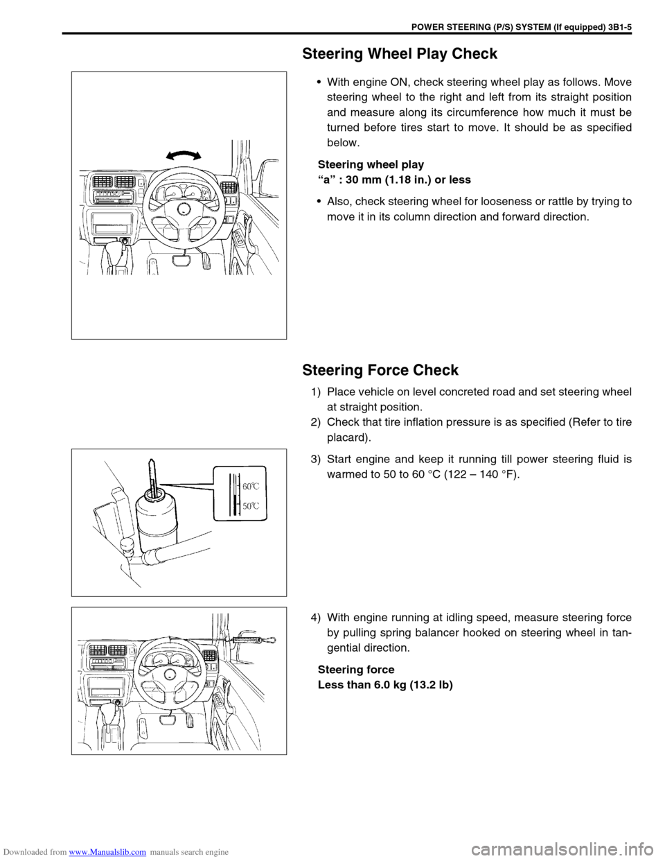
With engine ON, check steering wheel play as follows. Move
steering wheel to the right and left from its straight position
and measure along its circumference how much it must be
turned before tires start to move. It should be as specified
below.
Steering wheel play
“a” : 30 mm (1.18 in.) or less
Also, check steering wheel for looseness or rattle by trying to
move it in its column direction and forward direction.
Steering Force Check
1) Place vehicle on level concreted road and set steering wheel
at straight position.
2) Check that tire inflation pressure is as specified (Refer to tire
placard).
3) Start engine and keep it running till power steering fluid is
warmed to 50 to 60 °C (122 – 140 °F).
4) With engine running at idling speed, measure steering force
by pulling spring balancer hooked on steering wheel in tan-
gential direction.
Steering force
Less than 6.0 kg (13.2 lb)
Page 150 of 687
Downloaded from www.Manualslib.com manuals search engine POWER STEERING (P/S) SYSTEM (If equipped) 3B1-19
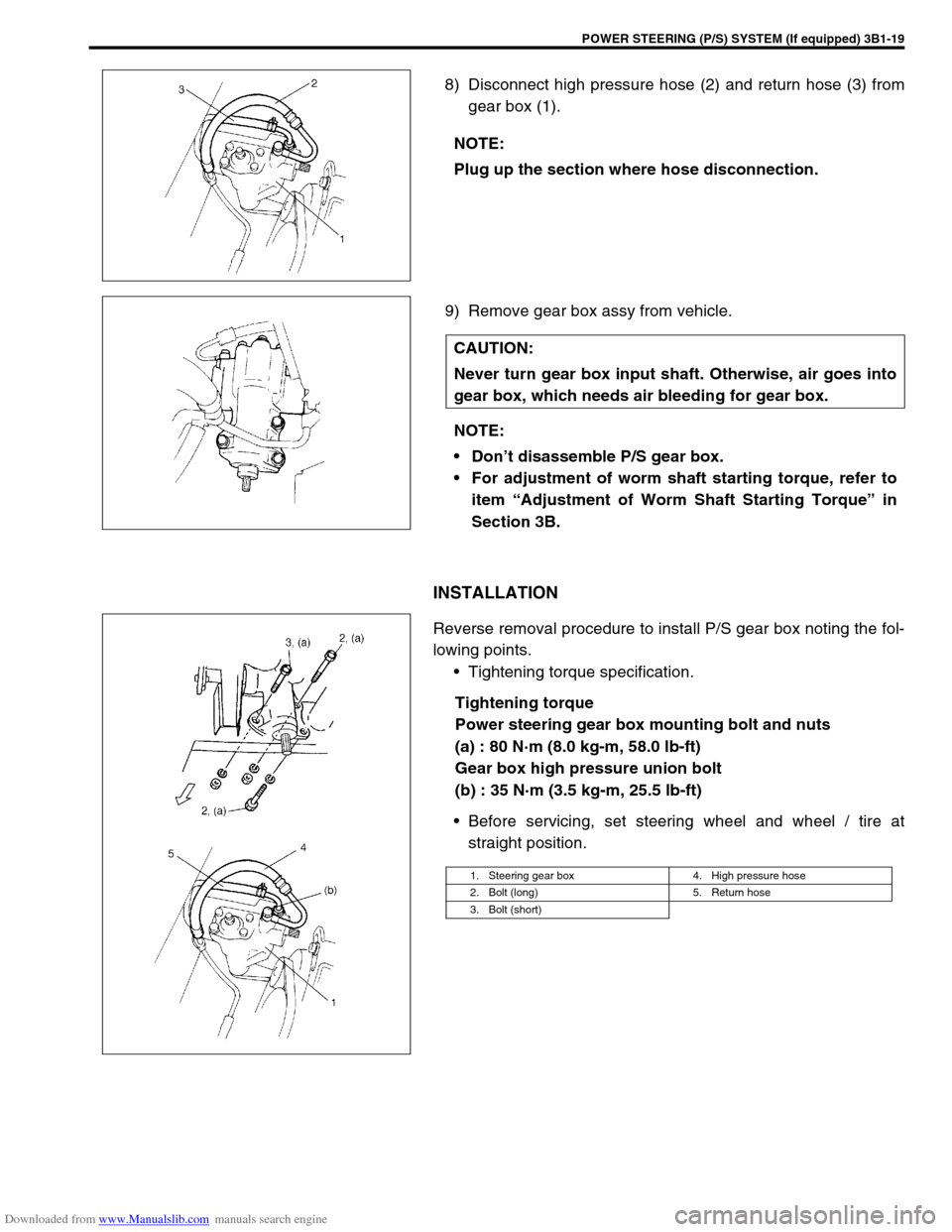
8) Disconnect high pressure hose (2) and return hose (3) from
gear box (1).
9) Remove gear box assy from vehicle.
INSTALLATION
Reverse removal procedure to install P/S gear box noting the fol-
lowing points.
Tightening torque specification.
Tightening torque
Power steering gear box mounting bolt and nuts
(a) : 80 N·m (8.0 kg-m, 58.0 lb-ft)
Gear box high pressure union bolt
(b) : 35 N·m (3.5 kg-m, 25.5 lb-ft)
Before servicing, set steering wheel and wheel / tire at
straight position. NOTE:
Plug up the section where hose disconnection.
CAUTION:
Never turn gear box input shaft. Otherwise, air goes into
gear box, which needs air bleeding for gear box.
NOTE:
Don’t disassemble P/S gear box.
For adjustment of worm shaft starting torque, refer to
item “Adjustment of Worm Shaft Starting Torque” in
Section 3B.
1. Steering gear box 4. High pressure hose
2. Bolt (long) 5. Return hose
3. Bolt (short)
Page 187 of 687
Downloaded from www.Manualslib.com manuals search engine 3D-14 FRONT SUSPENSION
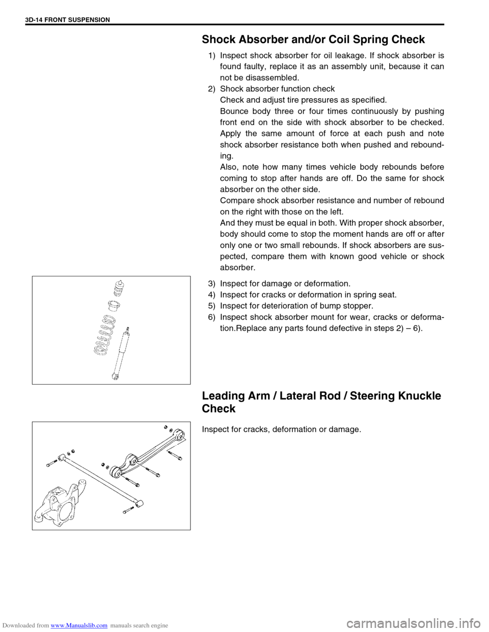
Shock Absorber and/or Coil Spring Check
1) Inspect shock absorber for oil leakage. If shock absorber is
found faulty, replace it as an assembly unit, because it can
not be disassembled.
2) Shock absorber function check
Check and adjust tire pressures as specified.
Bounce body three or four times continuously by pushing
front end on the side with shock absorber to be checked.
Apply the same amount of force at each push and note
shock absorber resistance both when pushed and rebound-
ing.
Also, note how many times vehicle body rebounds before
coming to stop after hands are off. Do the same for shock
absorber on the other side.
Compare shock absorber resistance and number of rebound
on the right with those on the left.
And they must be equal in both. With proper shock absorber,
body should come to stop the moment hands are off or after
only one or two small rebounds. If shock absorbers are sus-
pected, compare them with known good vehicle or shock
absorber.
3) Inspect for damage or deformation.
4) Inspect for cracks or deformation in spring seat.
5) Inspect for deterioration of bump stopper.
6) Inspect shock absorber mount for wear, cracks or deforma-
tion.Replace any parts found defective in steps 2) – 6).
Leading Arm / Lateral Rod / Steering Knuckle
Check
Inspect for cracks, deformation or damage.
Page 245 of 687

Downloaded from www.Manualslib.com manuals search engine 3F-2 WHEELS AND TIRES
General Description
Tires
This vehicle is equipped with following tire.
Tire size
: 205/70 R15 or 175/80 R15
The tires are of tubeless type. The tires are designed to operate satisfactorily with loads up to the full rated load
capacity when inflated to the recommended inflation pressure.
Correct tire pressures and driving habits have an important influence on tire life Heavy cornering, excessively
rapid acceleration, and unnecessary sharp braking increase tire wear.
Wheels
Standard equipment wheels are following steel wheels.
15 x 5 1/2 JJ
Replacement Tires
When replacement is necessary, the original equipment type tire should be used. Refer to the Tire Placard.
Replacement tires should be of the same size, load range and construction as those originally on the vehicle.
Use of any other size or type tire may affect ride, handling, speedometer / odometer calibration, vehicle ground
clearance and tire or snow chain clearance to the body and chassis.
It is recommended that new tires be installed in pairs on the same axle. If necessary to replace only one tire, it
should be paired with the tire having the most tread, to equalize braking traction.
The metric term for tire inflation pressure is the kilopascal (kPa).
Tire pressures will usually be printed in both kPa and psi on the
Tire Placard. Metric tire gauges are available from tool suppliers.
The following chart, converts commonly used inflation pressures
from kPa to psi. WARNING:
Do not mix different types of tires on the same vehicle such as radial, bias and bias-belted tires except
in emergencies, because vehicle handling may be seriously affected and may result in loss of control.
kPa
kgf/cm2psi
160
180
200
220
240
260
280
300
320
3401.6
1.8
2.0
2.2
2.4
2.6
2.8
3.0
3.2
3.423
26
29
32
35
38
41
44
47
50
Page 249 of 687
Downloaded from www.Manualslib.com manuals search engine 3F-6 WHEELS AND TIRES
Maintenance and Minor Adjustments
Wheel and Tire
Wheel repairs that use welding, heating, or peening are not approved. All damaged wheels should be replaced.
Studs
If a broken stud is found, see Section 3E (rear) or Section 3D (front) for Note and Replacement procedure.
Matched tires and wheels
(For vehicle equipped with steel wheels)
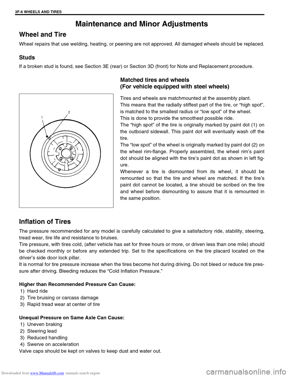
Tires and wheels are matchmounted at the assembly plant.
This means that the radially stiffest part of the tire, or “high spot”,
is matched to the smallest radius or “low spot” of the wheel.
This is done to provide the smoothest possible ride.
The “high spot” of the tire is originally marked by paint dot (1) on
the outboard sidewall. This paint dot will eventually wash off the
tire.
The “low spot” of the wheel is originally marked by paint dot (2) on
the wheel rim-flange. Properly assembled, the wheel rim’s paint
dot should be aligned with the tire’s paint dot as shown in left fig-
ure.
Whenever a tire is dismounted from its wheel, it should be
remounted so that the tire and wheel are matched. If the tire’s
paint dot cannot be located, a line should be scribed on the tire
and wheel before dismounting to assure that it is remounted in
the same position.
Inflation of Tires
The pressure recommended for any model is carefully calculated to give a satisfactory ride, stability, steering,
tread wear, tire life and resistance to bruises.
Tire pressure, with tires cold, (after vehicle has set for three hours or more, or driven less than one mile) should
be checked monthly or before any extended trip. Set to the specifications on the tire placard located on the
driver’s side door lock pillar.
It is normal for tire pressure increase when the tires become hot during driving. Do not bleed or reduce tire pres-
sure after driving. Bleeding reduces the “Cold Inflation Pressure.”
Higher than Recommended Pressure Can Cause:
1) Hard ride
2) Tire bruising or carcass damage
3) Rapid tread wear at center of tire
Unequal Pressure on Same Axle Can Cause:
1) Uneven braking
2) Steering lead
3) Reduced handling
4) Swerve on acceleration
Valve caps should be kept on valves to keep dust and water out.
Page 250 of 687
Downloaded from www.Manualslib.com manuals search engine WHEELS AND TIRES 3F-7
Lower than Recommended Pressure Can Cause:
1) Tire squeal on turns
2) Hard steering
3) Rapid and uneven wear on the edges of the tread
4) Tire rim bruises and rupture
5) Tire cord breakage
6) High tire temperatures
7) Reduced handling
8) High fuel consumption
Tire placard
The tire placard is located on the driver’s side door lock pillar and should be referred to for tire information. The
placard lists the maximum load, tire size and cold tire pressure where applicable.
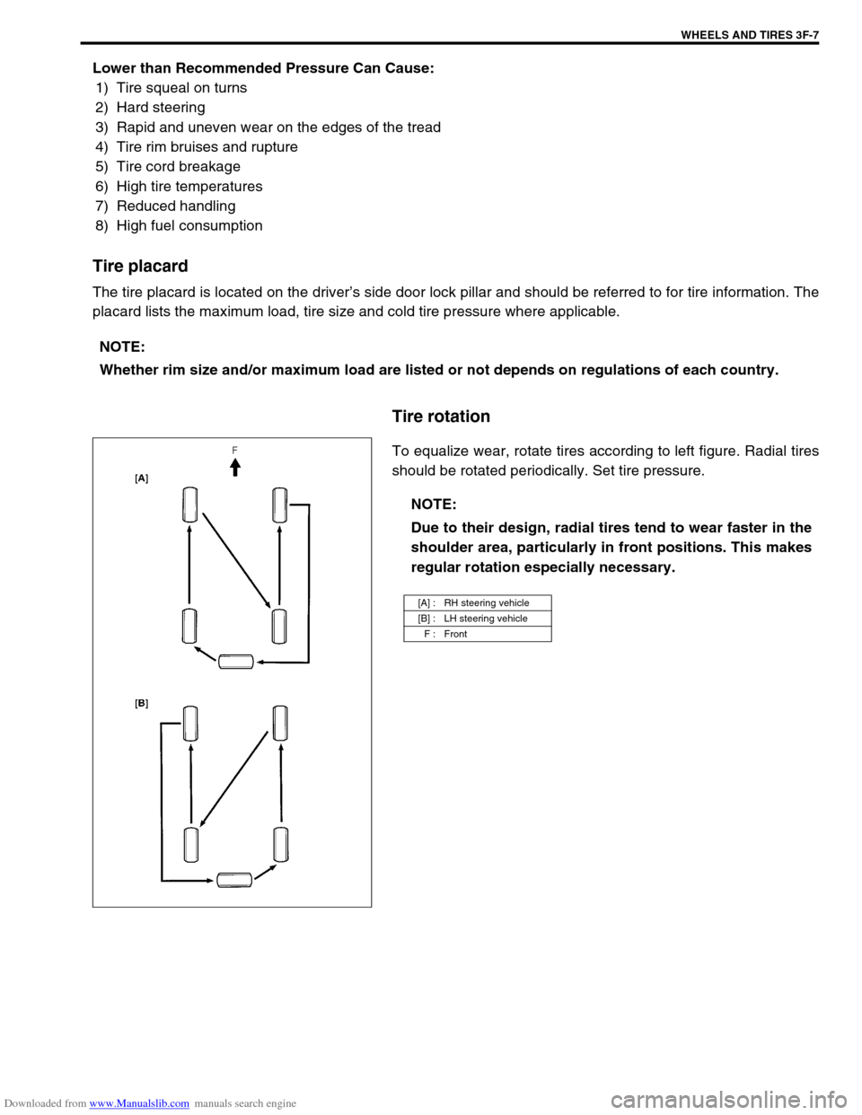
Tire rotation
To equalize wear, rotate tires according to left figure. Radial tires
should be rotated periodically. Set tire pressure. NOTE:
Whether rim size and/or maximum load are listed or not depends on regulations of each country.
NOTE:
Due to their design, radial tires tend to wear faster in the
shoulder area, particularly in front positions. This makes
regular rotation especially necessary.
[A] : RH steering vehicle
[B] : LH steering vehicle
F : Front
Page 252 of 687

Downloaded from www.Manualslib.com manuals search engine WHEELS AND TIRES 3F-9
Tire
Mounting and demounting
Use tire changing machine to mount or demount tires. Follow equipment manufacturer’s instructions. Do not use
hand tools or tire irons alone to change tires as they may damage tire beads or wheel rim.
Rim bead seats should be cleaned with wire brush or coarse steel wool to remove lubricants, old rubber and
light rust. Before mounting or demounting tire, bead area should be well lubricated with approved tire lubricant.
After mounting, inflate to 240 kPa (35 psi) so that beads are completely seated. Then adjust pressure to speci-
fied shown on tire placard.
Install valve core and inflate to proper pressure.
Repair
There are many different materials and techniques on the market to repair tires. As not all of these work on all
types of tires, tire manufacturers have published detailed instructions on how and when to repair tires. These
instructions can be obtained from the tire manufacturer.WARNING:
Do not stand over tire when inflating. Bead may break when bead snaps over rim’s safety hump and
cause serious personal injury.
Do not exceed 240 kPa (35 psi) pressure when inflating. If 240 kPa (35 psi) pressure will not seat
beads, deflate, re-lubricate and reinflate. Over inflation may cause bead to break and cause serious
personal injury.