Page 265 of 687

Downloaded from www.Manualslib.com manuals search engine 5-4 BRAKES
Diagnosis
Road Testing Brakes
Brakes should be tested on dry, clean, smooth and reasonably level roadway which is not crowned. Road test
brakes by making brake applications with both light and heavy pedal forces at various speeds to determine if the
vehicle stops evenly and effectively.
Also drive vehicle to see if it leads to one side or the other without brake application. If it does, check the tire
pressure, front end alignment and front suspension attachments for looseness. See diagnosis table for other
causes.
Brake Fluid Leaks
Check the master cylinder fluid levels. While a slight drop in reservoir level does result from normal lining wear,
an abnormally low level indicates a leak in the system. In such a case, check the entire brake system for leak-
age. If even a slight evidence of leakage is noted, the cause should be corrected or defective parts should be
replaced.
If fluid level is lower than the minimum level of reservoir, refilling is necessary. Fill reservoir with specified brake
fluid.
Brake fluid: Refer to reservoir tank cap.
Substandard or Contaminated Brake Fluid
Improper brake fluid, mineral oil or water in the fluid may cause the brake fluid to boil or the rubber components
in the hydraulic system to deteriorate.
If primary piston cups are swollen, then rubber parts have deteriorated. This deterioration may also be evi-
denced by swollen wheel cylinder piston cups on the drum brake wheels.
If deterioration of rubber is evident, disassemble all hydraulic parts and wash with alcohol. Dry these parts with
compressed air before assembly to keep alcohol out of the system. Replace all rubber parts in the system,
including hoses. Also, when working on the brake mechanisms, check for fluid on the linings. If excessive fluid is
found, replace the linings.
If master cylinder piston seals are satisfactory, check for leakage or excessive heat conditions. If condition is not
found, drain fluid, flush with brake fluid, refill and bleed the system.
The system must be flushed if there is any doubt as to the grade of fluid in the system or if fluid has been used
which contained parts that have been subjected to contaminated fluid.CAUTION:
Since brake system of this vehicle is factory-filled with brake fluid indicated on reservoir tank cap, do
not use or mix different type of fluid when refilling; otherwise serious damage will occur.
Do not use old or used brake fluid, or any fluid from a unsealed container.
Page 276 of 687

Downloaded from www.Manualslib.com manuals search engine BRAKES 5-15
Fluid Pressure Test (If Equipped with LSPV)
Test procedure for LSPV assembly is as follows.
Before testing, confirm the following.
Fuel tank is filled with fuel fully.
Vehicle is equipped with spare tire, tools, jack and jack han-
dle.
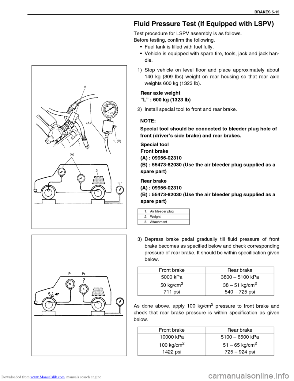
1) Stop vehicle on level floor and place approximately about
140 kg (309 Ibs) weight on rear housing so that rear axle
weights 600 kg (1323 Ib).
Rear axle weight
“L” : 600 kg (1323 lb)
2) Install special tool to front and rear brake.
Special tool
Front brake
(A) : 09956-02310
(B) : 55473-82030 (Use the air bleeder plug supplied as a
spare part)
Rear brake
(A) : 09956-02310
(B) : 55473-82030 (Use the air bleeder plug supplied as a
spare part)
3) Depress brake pedal gradually till fluid pressure of front
brake becomes as specified below and check corresponding
pressure of rear brake. It should be within specification given
below.
As done above, apply 100 kg/cm
2 pressure to front brake and
check that rear brake pressure is within specification as given
below.NOTE:
Special tool should be connected to bleeder plug hole of
front (driver’s side brake) and rear brakes.
1. Air bleeder plug
2. Weight
3. Attachment
Front brake Rear brake
5000 kPa
50 kg/cm
2
711 psi3800 – 5100 kPa
38 – 51 kg/cm
2
540 – 725 psi
Front brake Rear brake
10000 kPa
100 kg/cm
2
1422 psi5100 – 6500 kPa
51 – 65 kg/cm
2
725 – 924 psi
Page 279 of 687

Downloaded from www.Manualslib.com manuals search engine 5-18 BRAKES
4) When fluid pressure in the cylinder is almost depleted,
retighten bleeder plug.
5) Repeat this operation until there are no more air bubbles in
hydraulic line.
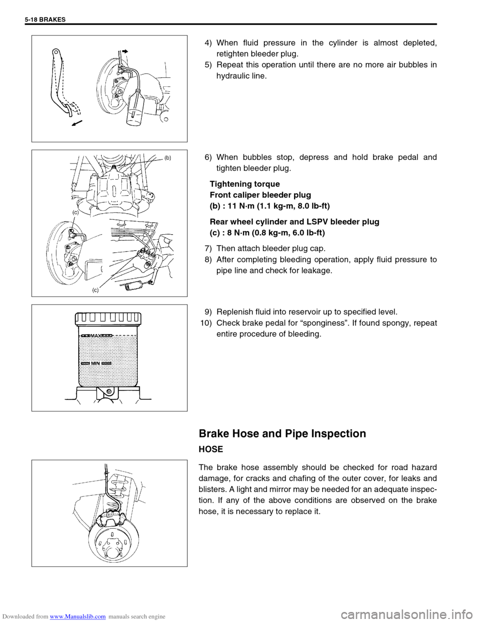
6) When bubbles stop, depress and hold brake pedal and
tighten bleeder plug.
Tightening torque
Front caliper bleeder plug
(b) : 11 N·m (1.1 kg-m, 8.0 lb-ft)
Rear wheel cylinder and LSPV bleeder plug
(c) : 8 N·m (0.8 kg-m, 6.0 lb-ft)
7) Then attach bleeder plug cap.
8) After completing bleeding operation, apply fluid pressure to
pipe line and check for leakage.
9) Replenish fluid into reservoir up to specified level.
10) Check brake pedal for “sponginess”. If found spongy, repeat
entire procedure of bleeding.
Brake Hose and Pipe Inspection
HOSE
The brake hose assembly should be checked for road hazard
damage, for cracks and chafing of the outer cover, for leaks and
blisters. A light and mirror may be needed for an adequate inspec-
tion. If any of the above conditions are observed on the brake
hose, it is necessary to replace it.
Page 382 of 687

Downloaded from www.Manualslib.com manuals search engine ENGINE GENERAL INFORMATION AND DIAGNOSIS 6-25
Excessive detonation
(The engine makes
sharp metallic knocks
that change with throt-
tle opening.
Sounds like pop corn
popping.)Engine overheating Refer to “Overheating” of this table.
Faulty spark plug Spark plugs in Section 6F.
Clogged fuel filter and fuel lines Diagnostic Flow Table B-3
Malfunctioning EGR valve (if equipped) EGR system in Section 6E.
Poor performance of knock sensor, ECT
sensor or MAP sensorKnock sensor in this section, ECT
sensor or MAP sensor in Section 6E.
Faulty injector Diagnostic Flow Table B-1
Faulty ECM Inspection of ECM and its circuit in
this section.
Excessive combustion chamber deposits Piston and cylinder head in Section
6A1.
Overheating
Inoperative thermostat Thermostat in Section 6B.
Faulty A/C condenser fan motor or its cir-
cuitA/C condenser fan control system
check in Section 6E.
Loose or slip water pump belt ITEM1-1 Drive belt inspection and
change in Section 0B.
Poor water pump performance Water pump in Section 6B.
Clogged or leaky radiator Radiator in Section 6B.
Improper engine oil grade ITEM1-3 Engine oil and oil filter
change in Section 0B.
Clogged oil filter or oil strainer Oil pressure check in Section 6A1.
Poor oil pump performance Oil pressure check in Section 6A1.
Dragging brakes Diagnosis Table in Section 5.
Slipping clutch Diagnosis Table in Section 7C.
Blown cylinder head gasket Valves and cylinder head in Section
6A1.
Poor gasoline mileage
Faulty ignition coil Ignition coil assembly in Section 6F.
Fuel pressure out of specification Diagnostic Flow Table B-3
Faulty TP sensor, ECT sensor or MAP
sensorTP sensor, ECT sensor or MAP sen-
sor in Section 6E.
Faulty injector Diagnostic Flow Table B-1
Faulty ECM Inspection of ECM and its circuit in
this section.
Malfunctioning EGR valve (if equipped) EGR system in Section 6E.
High idle speed Refer to item “Improper Engine Idle
Speed” previously outlined.
Low compression Previously outlined.
Poor valve seating Valves and cylinder head in Section
6A1.
Dragging brakes Diagnosis Table in Section 5.
Slipping clutch Diagnosis Table in Section 7C.
Thermostat out of order Thermostat in Section 6B.
Improper tire pressure Refer to Section 3F. Condition Possible Cause Reference Item
Page:
< prev 1-8 9-16 17-24