2005 SUZUKI JIMNY tank
[x] Cancel search: tankPage 180 of 687

Downloaded from www.Manualslib.com manuals search engine FRONT SUSPENSION 3D-7
4WD
→ 2WD
When the transfer shift control lever is shifted from the 4WD (4H or 4L) to the 2WD (2H) position, the 4WD con-
troller activates VSV1 and the intake manifold vacuum is applied to the chamber “A” in the hub housing. As the
slide gear is shifted to the wheel side by the vacuum force and disengaged from the outer gear, rotation of the
front wheel hub is not transmitted to the front axle shaft.
1. EPI & A/C controller 8. Engine speed signal 15. Chamber A 22. Slide gear
2. 4WD controller 9. Intake manifold 16. Piston A 23. Wheel hub
3. 4WD indicator lamp 10. Check valve 17. Magnet 24. Spindle
4.4WD switch 11. Vacuum tank 18. Housing 25. Front axle shaft
5. A/C switch (if equipped) 12. VSV1 19. Spring 26. To opposite side
6. Vacuum switch 13. VSV2 20. Diaphragm 27. A/C controller
7. A/C cut signal (if equipped) 14. Outer gear 21. Sleeve A: Vacuum circuit
Page 181 of 687

Downloaded from www.Manualslib.com manuals search engine 3D-8 FRONT SUSPENSION
Diagnosis
Diagnosis Table
For description not found in the table below, refer to “Diagnosis Table” in Section 3.
4WD CONTROL SYSTEM
4WD CONTROL SYSTEM DIAGNOSTIC FLOW TABLE
Before performing the trouble diagnosis, check that the air locking hub assemblies are in good condition and
there is no air leakage from vacuum hoses and vacuum pipe. Refer to “4WD Control System Check” in this sec-
tion for air leakage.
[NOTES ON SYSTEM CIRCUIT INSPECTION]
Be sure to read “Precautions for Electrical Circuit Service” in Section 0A before circuit inspection and
observe what is written there.
For system circuit, refer to the figure of “System Circuit” in this section. Condition Possible Cause Correction
4WD Indicator light
flashingHub locking procedure error
Defective VSV2
Defective vacuum switch
Defective check valve or vacuum tank
Air leak from vacuum circuit
Clogged vacuum hose or pipe
Faulty 4WD controllerShift transfer shift control lever
2WD → 4WD once again
Replace
Replace
Replace
Check and repair
Replace
Check and replace
2WD/4WD switching
errorDefective air locking hub assembly
Abnormality in 4WD control system
Air leakage from vacuum circuit
Clogged vacuum hose or pipe
Defective check valve or vacuum tankReplace
Inspect referring to “4WD Control
System Diagnostic Flow Table”
Check and replace
Replace
Replace
Step Action Yes No
1 Check ground circuit.
1) Disconnect coupler from 4WD controller
with ignition switch OFF.
2) Check for proper connection to 4WD con-
troller at all terminals.
3) If OK, check continuity between A5 terminal
and body ground.
Is there continuity between A5 terminal and
body ground?Go to Step 2.“B” wire is open.
2 Check power circuit.
1) Disconnect coupler from 4WD controller.
2) Turn ignition switch ON.
3) Check voltage between A10 terminal and
ground.
Is it 10 – 14 V?Go to Step 3.“Y/R” circuit is open or
short.
Page 265 of 687

Downloaded from www.Manualslib.com manuals search engine 5-4 BRAKES
Diagnosis
Road Testing Brakes
Brakes should be tested on dry, clean, smooth and reasonably level roadway which is not crowned. Road test
brakes by making brake applications with both light and heavy pedal forces at various speeds to determine if the
vehicle stops evenly and effectively.
Also drive vehicle to see if it leads to one side or the other without brake application. If it does, check the tire
pressure, front end alignment and front suspension attachments for looseness. See diagnosis table for other
causes.
Brake Fluid Leaks
Check the master cylinder fluid levels. While a slight drop in reservoir level does result from normal lining wear,
an abnormally low level indicates a leak in the system. In such a case, check the entire brake system for leak-
age. If even a slight evidence of leakage is noted, the cause should be corrected or defective parts should be
replaced.
If fluid level is lower than the minimum level of reservoir, refilling is necessary. Fill reservoir with specified brake
fluid.
Brake fluid: Refer to reservoir tank cap.
Substandard or Contaminated Brake Fluid
Improper brake fluid, mineral oil or water in the fluid may cause the brake fluid to boil or the rubber components
in the hydraulic system to deteriorate.
If primary piston cups are swollen, then rubber parts have deteriorated. This deterioration may also be evi-
denced by swollen wheel cylinder piston cups on the drum brake wheels.
If deterioration of rubber is evident, disassemble all hydraulic parts and wash with alcohol. Dry these parts with
compressed air before assembly to keep alcohol out of the system. Replace all rubber parts in the system,
including hoses. Also, when working on the brake mechanisms, check for fluid on the linings. If excessive fluid is
found, replace the linings.
If master cylinder piston seals are satisfactory, check for leakage or excessive heat conditions. If condition is not
found, drain fluid, flush with brake fluid, refill and bleed the system.
The system must be flushed if there is any doubt as to the grade of fluid in the system or if fluid has been used
which contained parts that have been subjected to contaminated fluid.CAUTION:
Since brake system of this vehicle is factory-filled with brake fluid indicated on reservoir tank cap, do
not use or mix different type of fluid when refilling; otherwise serious damage will occur.
Do not use old or used brake fluid, or any fluid from a unsealed container.
Page 276 of 687

Downloaded from www.Manualslib.com manuals search engine BRAKES 5-15
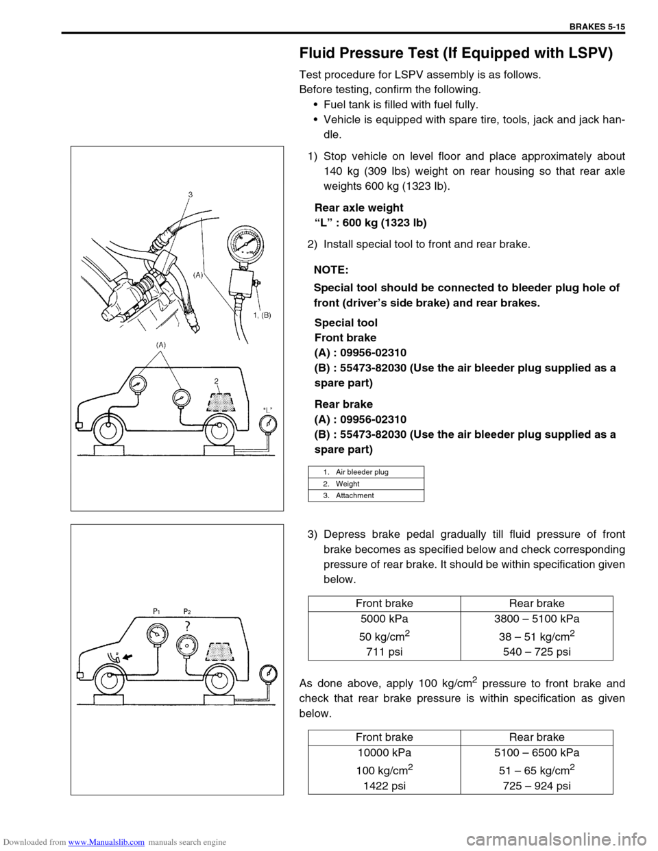
Fluid Pressure Test (If Equipped with LSPV)
Test procedure for LSPV assembly is as follows.
Before testing, confirm the following.
Fuel tank is filled with fuel fully.
Vehicle is equipped with spare tire, tools, jack and jack han-
dle.
1) Stop vehicle on level floor and place approximately about
140 kg (309 Ibs) weight on rear housing so that rear axle
weights 600 kg (1323 Ib).
Rear axle weight
“L” : 600 kg (1323 lb)
2) Install special tool to front and rear brake.
Special tool
Front brake
(A) : 09956-02310
(B) : 55473-82030 (Use the air bleeder plug supplied as a
spare part)
Rear brake
(A) : 09956-02310
(B) : 55473-82030 (Use the air bleeder plug supplied as a
spare part)
3) Depress brake pedal gradually till fluid pressure of front
brake becomes as specified below and check corresponding
pressure of rear brake. It should be within specification given
below.
As done above, apply 100 kg/cm
2 pressure to front brake and
check that rear brake pressure is within specification as given
below.NOTE:
Special tool should be connected to bleeder plug hole of
front (driver’s side brake) and rear brakes.
1. Air bleeder plug
2. Weight
3. Attachment
Front brake Rear brake
5000 kPa
50 kg/cm
2
711 psi3800 – 5100 kPa
38 – 51 kg/cm
2
540 – 725 psi
Front brake Rear brake
10000 kPa
100 kg/cm
2
1422 psi5100 – 6500 kPa
51 – 65 kg/cm
2
725 – 924 psi
Page 303 of 687

Downloaded from www.Manualslib.com manuals search engine 5-42 BRAKES
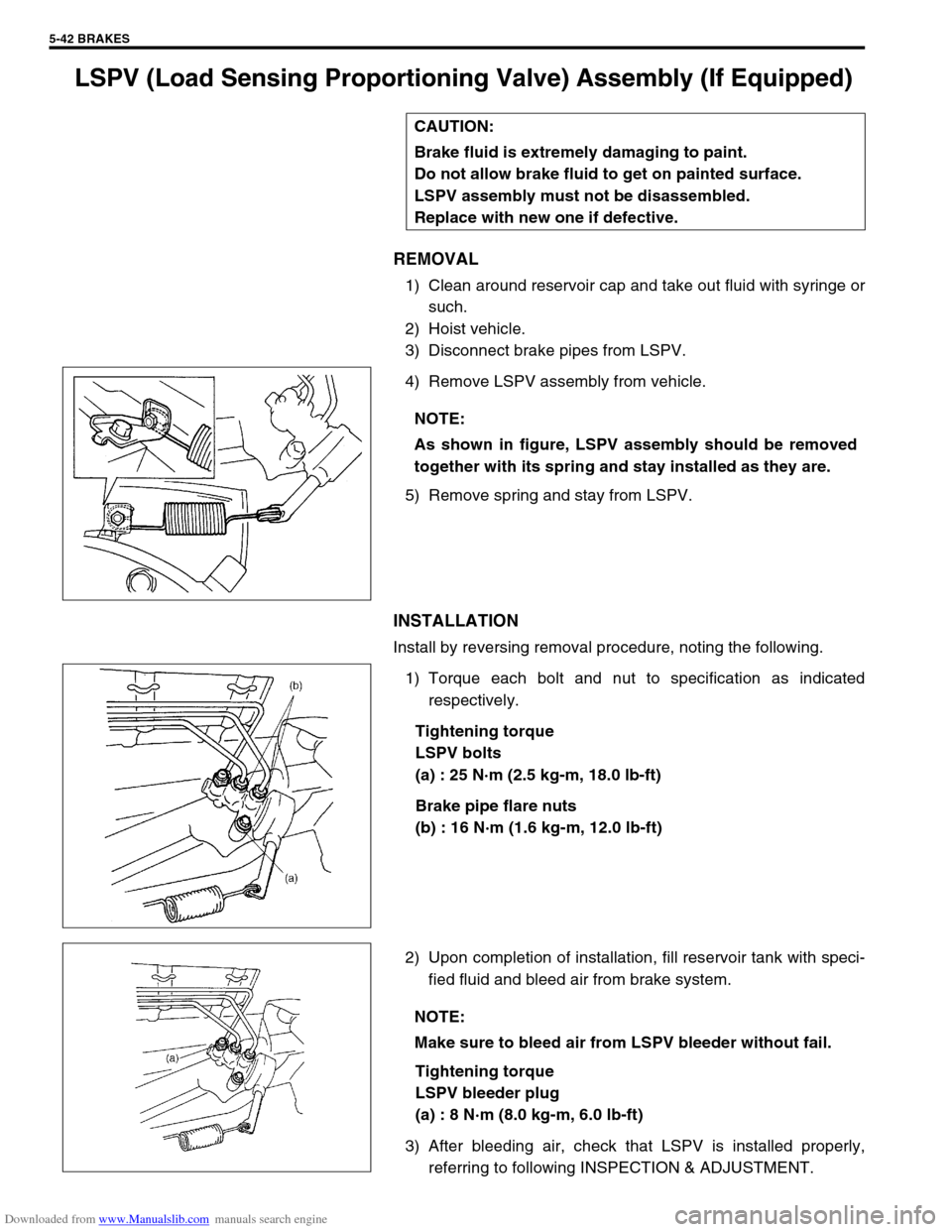
LSPV (Load Sensing Proportioning Valve) Assembly (If Equipped)
REMOVAL
1) Clean around reservoir cap and take out fluid with syringe or
such.
2) Hoist vehicle.
3) Disconnect brake pipes from LSPV.
4) Remove LSPV assembly from vehicle.
5) Remove spring and stay from LSPV.
INSTALLATION
Install by reversing removal procedure, noting the following.
1) Torque each bolt and nut to specification as indicated
respectively.
Tightening torque
LSPV bolts
(a) : 25 N·m (2.5 kg-m, 18.0 lb-ft)
Brake pipe flare nuts
(b) : 16 N·m (1.6 kg-m, 12.0 lb-ft)
2) Upon completion of installation, fill reservoir tank with speci-
fied fluid and bleed air from brake system.
Tightening torque
LSPV bleeder plug
(a) : 8 N·m (8.0 kg-m, 6.0 lb-ft)
3) After bleeding air, check that LSPV is installed properly,
referring to following INSPECTION & ADJUSTMENT. CAUTION:
Brake fluid is extremely damaging to paint.
Do not allow brake fluid to get on painted surface.
LSPV assembly must not be disassembled.
Replace with new one if defective.
NOTE:
As shown in figure, LSPV assembly should be removed
together with its spring and stay installed as they are.
NOTE:
Make sure to bleed air from LSPV bleeder without fail.
Page 304 of 687

Downloaded from www.Manualslib.com manuals search engine BRAKES 5-43
LSPV Assembly
INSPECTION AND ADJUSTMENT
1) Confirm the following before inspection and adjustment.
Fuel tank is filled with fuel fully.
Vehicle is equipped with spare tire, tools, jack and jack han-
dle.
Vehicle is free from any other load.
Place it on level floor.
2) Push up LSPV lever with finger till it stops and measure
length of coil spring (“a” in figure).
3) Spring length “a” should be as specified.
Spring length “a”
147 mm (5.79 in.)
4) If it isn’t, adjust it to specification by changing stay position
as shown in figure. After adjustment, tighten bolt to specified
torque.
Tightening torque
LSPV adjust bolt
(a) : 25 N·m (2.5 kg-m, 18.0 lb-ft)
NOTE:
Check to make sure that LSPV body and brake pipe joints
are free from fluid leakage. Replace defective parts, if
any.
Page 312 of 687

Downloaded from www.Manualslib.com manuals search engine BRAKES 5-51
Rear Brake Hose/Pipe
REMOVAL
1) Raise, suitably support vehicle. Remove wheel if necessary.
2) Clean dirt and foreign material from both hose end or pipe end fittings. Remove brake hose and pipe.
INSTALLATION
1) Install brake hose and pipe by reversing removal procedure, noting the following points.
Fill and maintain brake fluid level in reservoir. Bleed brake system.
2) Perform brake test and check each installed part for fluid leakage.
CAUTION:
Position clamps to white marks on two brake pipes.
Be sure to obtain more than 3 mm (0.118 in.) clearance between axle housing and brake pipe.
Install clamps properly referring to figure below and tighten bolts.
When installing hose, make sure that it has no twist or kink.
T : Top side 2. Rear axle housing 5. Fuel tank 8. Brake pipe (vehicle with LSPV)
R : Right side 3. Rear wheel cylinder 6. Chassis frame a-b: Clamp
1. Clamp 4. LSPV (if equipped) 7. Fuel pipe Tightening torque
Page 315 of 687

Downloaded from www.Manualslib.com manuals search engine 5-54 BRAKES
Tightening Torque Specifications
Required Service Material
Fastening partTightening torque
Nm kg-m lb-ft
Brake caliper carrier bolt 85 8.5 61.5
Brake caliper pin bolt 22 2.2 16.0
Front brake flexible hose bolt 23 2.3 17.0
Rear brake back plate nut 23 2.3 17.0
Master cylinder nut 13 1.3 9.5
Booster nut 13 1.3 9.5
Brake pipe 5-way 4-way joint bolt 11 1.1 8.0
Brake pipe flare nut 16 1.6 12.0
LSPV bolt/P valve bolt 25 2.5 18.0
Brake bleeder plugFront caliper 11 1.1 8.0
Rear wheel cylinder, LSPV 8 0.8 6.0
Wheel nut 95 9.5 69.0
Hose bracket bolt 11 1.1 8.0
Booster clevis nut 25 2.5 18.0
Stop light switch lock nut 6.5 0.65 4.7
Parking brake lever bolt 23 2.3 17.0
Wheel cylinder mounting bolt 9 0.9 6.5
Piston stopper bolt 10 1.0 7.5
LSPV adjust bolt 25 2.5 18.0
Material Recommended SUZUKI products Use
Brake fluid Indicated on reservoir tank cap or
described in owner’s manual of vehi-
cleTo fill master cylinder reservoir.
To clean and apply to inner parts of master
cylinder caliper and wheel cylinder when they
are disassembled.
Water tight sealant SEALING COMPOUND 366E
99000-31090To apply to mating surfaces of brake back
plate and rear wheel cylinder.
Sealant SUZUKI BOND NO. 1215
99000-31110To apply to mating surfaces of brake back
plate and rear axle housing.
To apply to mating surfaces of brake back
plate and rear wheel bearing retainer.