Page 256 of 687
Downloaded from www.Manualslib.com manuals search engine PROPELLER SHAFTS 4B-3
On-Vehicle Service
Propeller Shafts
REMOVAL
1) Hoist vehicle.
2) Drain transmission oil only when servicing propeller shaft
No. 1.
3) Before removing propeller shaft (2), give match marks (1) on
each joint flange (3) and propeller shaft (2) as shown.
4) Remove propeller shaft(s).
INSPECTION
Inspect propeller shaft and flange yoke for damage, and propeller
shaft for runout.
If damage is found or shaft runout exceeds its limit, replace.
Propeller shaft runout limit : 0.8 mm (0.031 in.)
Page 257 of 687

Downloaded from www.Manualslib.com manuals search engine 4B-4 PROPELLER SHAFTS
INSTALLATION
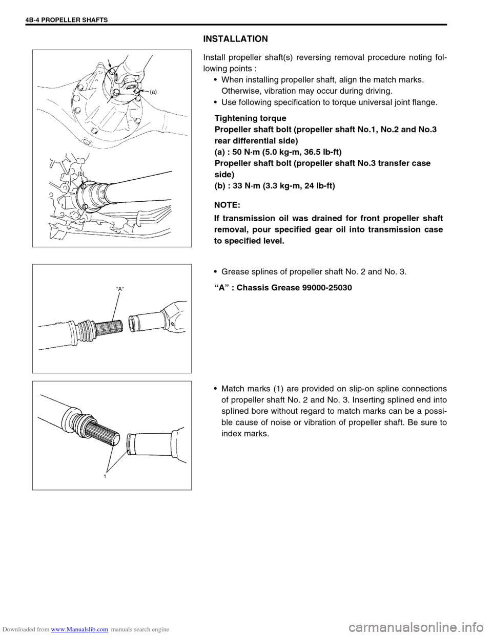
Install propeller shaft(s) reversing removal procedure noting fol-
lowing points :
When installing propeller shaft, align the match marks.
Otherwise, vibration may occur during driving.
Use following specification to torque universal joint flange.
Tightening torque
Propeller shaft bolt (propeller shaft No.1, No.2 and No.3
rear differential side)
(a) : 50 N·m (5.0 kg-m, 36.5 lb-ft)
Propeller shaft bolt (propeller shaft No.3 transfer case
side)
(b) : 33 N·m (3.3 kg-m, 24 lb-ft)
Grease splines of propeller shaft No. 2 and No. 3.
“A” : Chassis Grease 99000-25030
Match marks (1) are provided on slip-on spline connections
of propeller shaft No. 2 and No. 3. Inserting splined end into
spIined bore without regard to match marks can be a possi-
ble cause of noise or vibration of propeller shaft. Be sure to
index marks. NOTE:
If transmission oil was drained for front propeller shaft
removal, pour specified gear oil into transmission case
to specified level.
Page 258 of 687
Downloaded from www.Manualslib.com manuals search engine PROPELLER SHAFTS 4B-5
Universal Joint
DISASSEMBLY
1) Using special tool, remove 4 circlips (1).
Special tool
(A) : 09900-06108
2) Apply penetrate lubricant between bearing race outer diame-
ter and shaft yoke bore.
3) Using a set of special tool, push spider bearing race (1) out
3 – 4 mm (0.12 – 0.16 in.) from shaft yoke side face (2).
Special tool
(B) : 09926-48010
Pushed out value of bearing race from shaft yoke side
face
“a” : 3 – 4 mm (0.12 – 0.16 in.)
4) Tapping shaft yoke (2) with a hammer, remove bearing race
(1) from shaft yoke (2) completely.
5) Take out bearing race (1) on the opposite side of shaft yoke
(2) in the same way as shown.
Page 259 of 687
Downloaded from www.Manualslib.com manuals search engine 4B-6 PROPELLER SHAFTS
6) Push out bearing race (2) on flange yoke (1) in the same
way as Step 2).
7) Holding bearing race (2) by a vise (3), tap flange yoke (1)
and take out race.
8) Take out bearing race (2) on the opposite side of flange yoke
(1) in the same way as Step 5) to Step 6).
REASSEMBLY
1) Apply grease to rollers (1) in bearing races (2).
“A” : Grease 99000-25030
2) With spider (4) inserted into bearing race (2) to prevent roll-
ers in race from coming out, insert bearing race (2) into shaft
yoke (3) until it is flush with side face of shaft yoke (3), tap-
ping it by a copper hammer (1).
CAUTION:
Do not reuse spider (1), bearings (2) and circlips. Other-
wise it may damage propeller shaft or cause abnormal
vibration or noise.
NOTE:
Make sure that rollers (1) in bearing race (2) are all in
place.
Page 260 of 687

Downloaded from www.Manualslib.com manuals search engine PROPELLER SHAFTS 4B-7
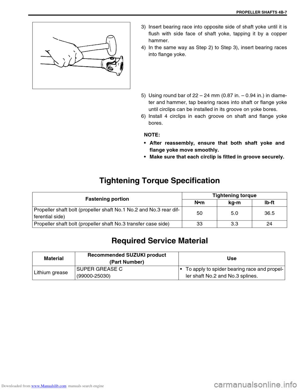
3) Insert bearing race into opposite side of shaft yoke until it is
flush with side face of shaft yoke, tapping it by a copper
hammer.
4) In the same way as Step 2) to Step 3), insert bearing races
into flange yoke.
5) Using round bar of 22 – 24 mm (0.87 in. – 0.94 in.) in diame-
ter and hammer, tap bearing races into shaft or flange yoke
until circlips can be installed in its groove on yoke bores.
6) Install 4 circlips in each groove on shaft and flange yoke
bores.
Tightening Torque Specification
Required Service Material
NOTE:
After reassembly, ensure that both shaft yoke and
flange yoke move smoothly.
Make sure that each circlip is fitted in groove securely.
Fastening portionTightening torque
Nm kg-m lb-ft
Propeller shaft bolt (propeller shaft No.1 No.2 and No.3 rear dif-
ferential side)50 5.0 36.5
Propeller shaft bolt (propeller shaft No.3 transfer case side) 33 3.3 24
MaterialRecommended SUZUKI product
(Part Number)Use
Lithium greaseSUPER GREASE C
(99000-25030)To apply to spider bearing race and propel-
ler shaft No.2 and No.3 splines.
Page 261 of 687
Downloaded from www.Manualslib.com manuals search engine 4B-8 PROPELLER SHAFTS
Special Tool
09900-06108 09926-48010
Snap ring pliers (Closing
type)Universal joint disassem-
bling tool set
Page 600 of 687

Downloaded from www.Manualslib.com manuals search engine ENGINE FUEL 6C-5
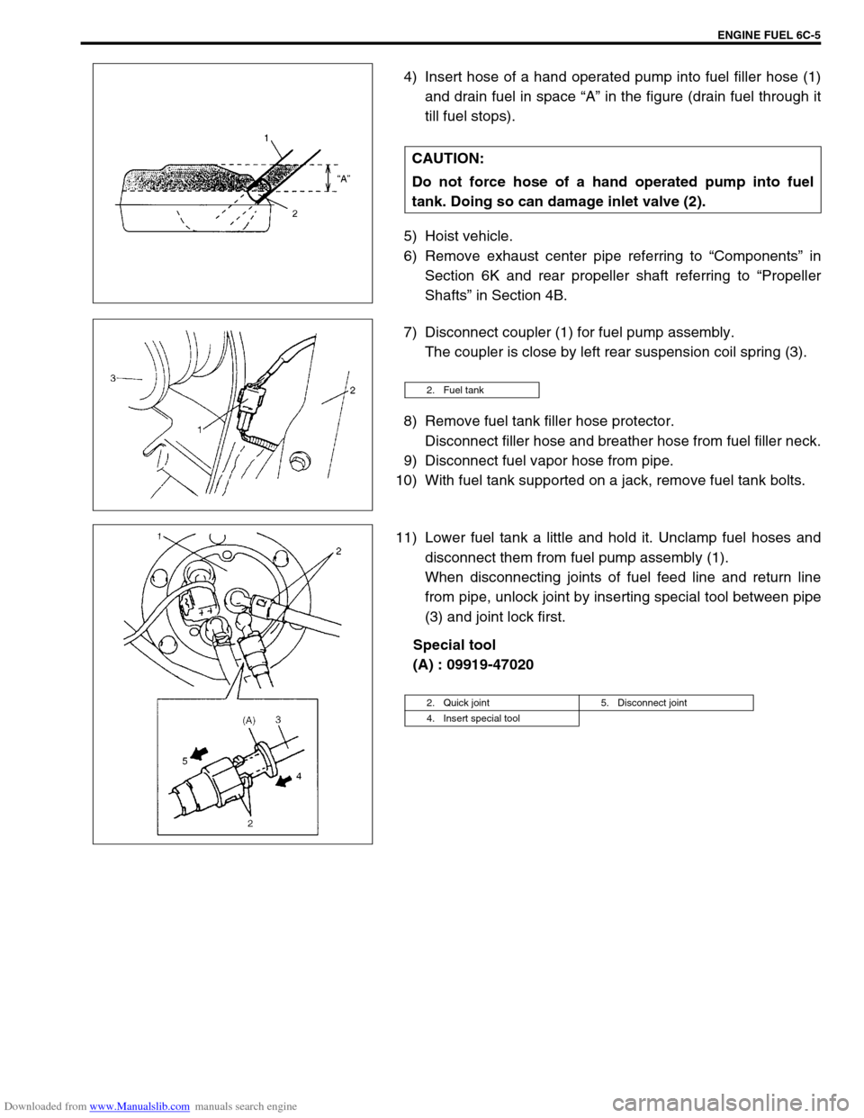
4) Insert hose of a hand operated pump into fuel filler hose (1)
and drain fuel in space “A” in the figure (drain fuel through it
till fuel stops).
5) Hoist vehicle.
6) Remove exhaust center pipe referring to “Components” in
Section 6K and rear propeller shaft referring to “Propeller
Shafts” in Section 4B.
7) Disconnect coupler (1) for fuel pump assembly.
The coupler is close by left rear suspension coil spring (3).
8) Remove fuel tank filler hose protector.
Disconnect filler hose and breather hose from fuel filler neck.
9) Disconnect fuel vapor hose from pipe.
10) With fuel tank supported on a jack, remove fuel tank bolts.
11) Lower fuel tank a little and hold it. Unclamp fuel hoses and
disconnect them from fuel pump assembly (1).
When disconnecting joints of fuel feed line and return line
from pipe, unlock joint by inserting special tool between pipe
(3) and joint lock first.
Special tool
(A) : 09919-47020 CAUTION:
Do not force hose of a hand operated pump into fuel
tank. Doing so can damage inlet valve (2).
2. Fuel tank
2. Quick joint 5. Disconnect joint
4. Insert special tool