Page 597 of 687
Downloaded from www.Manualslib.com manuals search engine 6C-2 ENGINE FUEL
General Description
Fuel System
The main components of the fuel system are fuel tank, fuel pump assembly with fuel filter and fuel level gauge
and fuel cut valve, fuel feed line, fuel return line and fuel vapor line.
For the details of fuel flow and fuel vapor flow, refer to “Fuel Delivery System” and “Emission Control System” in
Section 6E.
Fuel Tank
The fuel tank is located under the rear section of the vehicle. The
fuel pump assembly is installed in fuel tank. Whenever servicing
the fuel pump assembly, the fuel tank must be removed from the
vehicle.
1. Fuel tank 4. Fuel filler cap 7. Fuel vapor line 10. Fuel filler hose clamp
2. Fuel pump assembly 5. Fuel feed line 8. Fuel filler neck Tightening torque
3. Breather hose 6. Fuel return line 9. Fuel tank mounting bolt
Page 598 of 687

Downloaded from www.Manualslib.com manuals search engine ENGINE FUEL 6C-3
Fuel Pump Assembly
The fuel pump assembly (1) consists of fuel pump (6), fuel filter
(2), fuel level gauge (5) and fuel cut valve (4).
FUEL PUMP
For structure and operation of the fuel pump, refer to “Fuel Deliv-
ery System” in Section 6E.
FUEL CUT VALVE
The fuel cut valve consists of a float and a spring. It allows only
the fuel vapor to flow into the canister and prevents the fuel from
flowing into the canister.
Fuel Filler Cap
The fuel tank filler neck has a vacuum cap.
A ratchet tightening device on the threaded fuel filler cap reduces
the chances of incorrect installation, which would prevent sealing
fuel vapors.
After the gasket (2) on fuel filler cap and the filler neck flange con-
tact, the ratchet produces a loud clicking noise, indicating the seal
has been set.
This cap has a vacuum relief valve (1) inside.
The vacuum relief valve opens to relieve the vacuum created in
the fuel tank.
3. Suction filter
Page 603 of 687
Downloaded from www.Manualslib.com manuals search engine 6C-8 ENGINE FUEL
INSPECTION
Check fuel pump assembly for damage.
Check fuel suction filter (1) for evidence of dirt and contamination.
If present, replace or clean and check for presence of dirt in fuel
tank.
For inspection of fuel pump itself, refer to “Table B – 3 Fuel Pres-
sure Check” in Section 6.
For inspection of fuel level gauge, refer to “Fuel Meter / Fuel
Gauge Unit” in Section 8.
DISASSEMBLY / REASSEMBLY
2. Fuel filter & bracket assembly
3. Fuel pump motor & level gauge assembly
“A” : Apply oil 4. Housing 8. Cushion
1. Bracket sub assembly (including fuel filter) 5. Lead wire 9. Bracket
2. Grommet 6. Fuel level gauge 10. Spacer
3. Tube 7. Fuel pump
Page 610 of 687

Downloaded from www.Manualslib.com manuals search engine ENGINE AND EMISSION CONTROL SYSTEM 6E-5
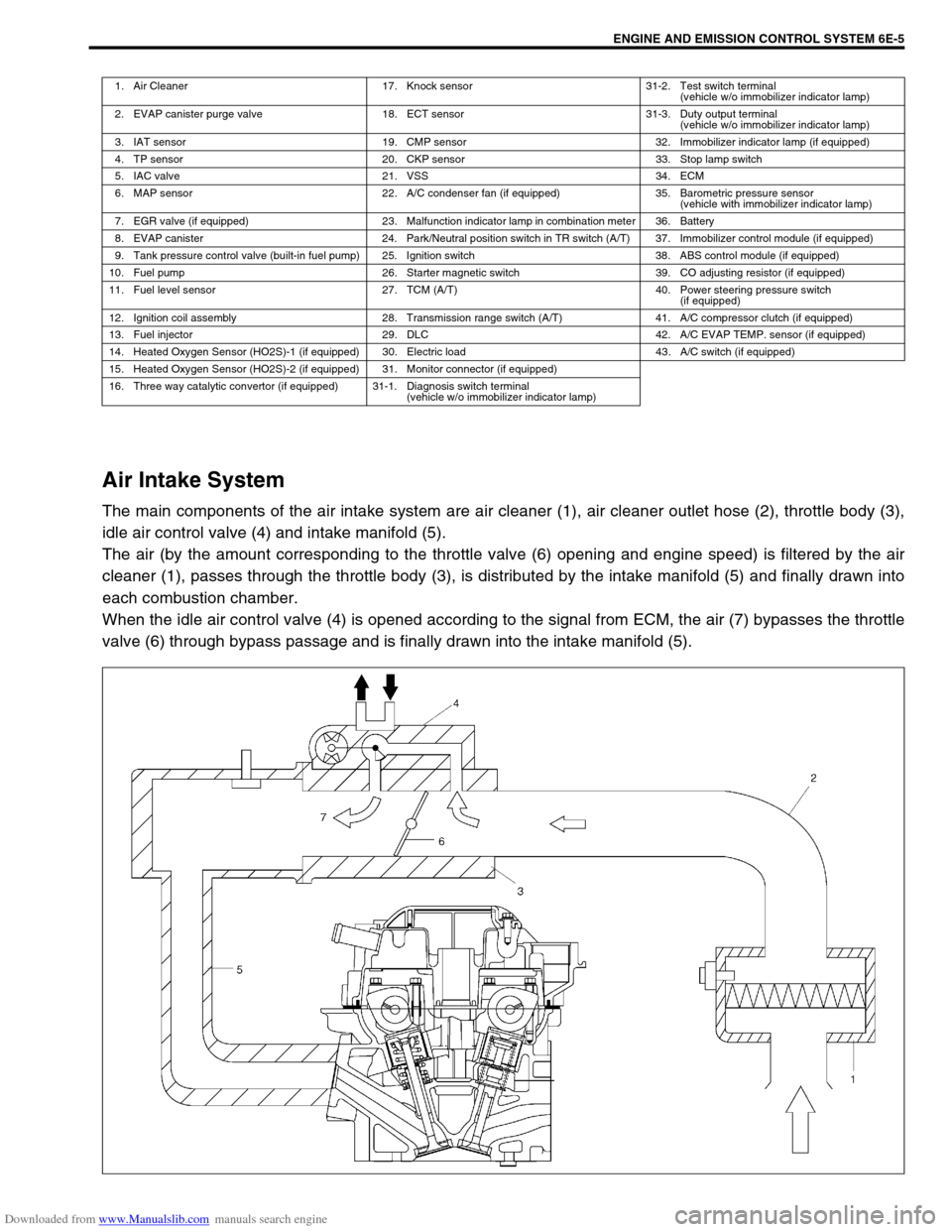
Air Intake System
The main components of the air intake system are air cleaner (1), air cleaner outlet hose (2), throttle body (3),
idle air control valve (4) and intake manifold (5).
The air (by the amount corresponding to the throttle valve (6) opening and engine speed) is filtered by the air
cleaner (1), passes through the throttle body (3), is distributed by the intake manifold (5) and finally drawn into
each combustion chamber.
When the idle air control valve (4) is opened according to the signal from ECM, the air (7) bypasses the throttle
valve (6) through bypass passage and is finally drawn into the intake manifold (5).
1. Air Cleaner 17. Knock sensor 31-2. Test switch terminal
(vehicle w/o immobilizer indicator lamp)
2. EVAP canister purge valve 18. ECT sensor 31-3. Duty output terminal
(vehicle w/o immobilizer indicator lamp)
3. IAT sensor 19. CMP sensor 32. Immobilizer indicator lamp (if equipped)
4. TP sensor 20. CKP sensor 33. Stop lamp switch
5. IAC valve 21. VSS 34. ECM
6. MAP sensor 22. A/C condenser fan (if equipped) 35. Barometric pressure sensor
(vehicle with immobilizer indicator lamp)
7. EGR valve (if equipped) 23. Malfunction indicator lamp in combination meter 36. Battery
8. EVAP canister 24. Park/Neutral position switch in TR switch (A/T) 37. Immobilizer control module (if equipped)
9. Tank pressure control valve (built-in fuel pump) 25. Ignition switch 38. ABS control module (if equipped)
10. Fuel pump 26. Starter magnetic switch 39. CO adjusting resistor (if equipped)
11. Fuel level sensor 27. TCM (A/T) 40. Power steering pressure switch
(if equipped)
12. Ignition coil assembly 28. Transmission range switch (A/T) 41. A/C compressor clutch (if equipped)
13. Fuel injector 29. DLC 42. A/C EVAP TEMP. sensor (if equipped)
14. Heated Oxygen Sensor (HO2S)-1 (if equipped) 30. Electric load 43. A/C switch (if equipped)
15. Heated Oxygen Sensor (HO2S)-2 (if equipped) 31. Monitor connector (if equipped)
16. Three way catalytic convertor (if equipped) 31-1. Diagnosis switch terminal
(vehicle w/o immobilizer indicator lamp)
Page 611 of 687

Downloaded from www.Manualslib.com manuals search engine 6E-6 ENGINE AND EMISSION CONTROL SYSTEM
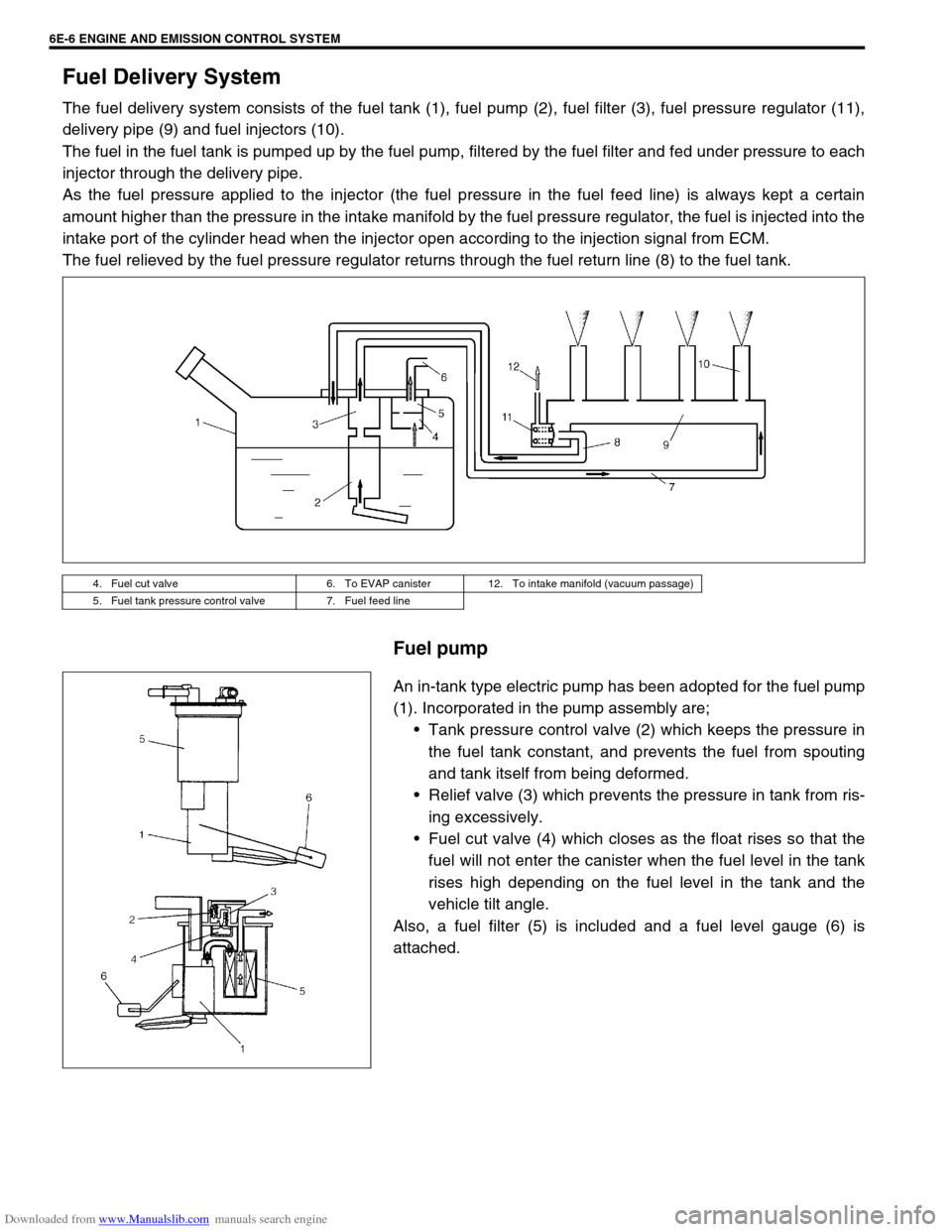
Fuel Delivery System
The fuel delivery system consists of the fuel tank (1), fuel pump (2), fuel filter (3), fuel pressure regulator (11),
delivery pipe (9) and fuel injectors (10).
The fuel in the fuel tank is pumped up by the fuel pump, filtered by the fuel filter and fed under pressure to each
injector through the delivery pipe.
As the fuel pressure applied to the injector (the fuel pressure in the fuel feed line) is always kept a certain
amount higher than the pressure in the intake manifold by the fuel pressure regulator, the fuel is injected into the
intake port of the cylinder head when the injector open according to the injection signal from ECM.
The fuel relieved by the fuel pressure regulator returns through the fuel return line (8) to the fuel tank.
Fuel pump
An in-tank type electric pump has been adopted for the fuel pump
(1). Incorporated in the pump assembly are;
Tank pressure control valve (2) which keeps the pressure in
the fuel tank constant, and prevents the fuel from spouting
and tank itself from being deformed.
Relief valve (3) which prevents the pressure in tank from ris-
ing excessively.
Fuel cut valve (4) which closes as the float rises so that the
fuel will not enter the canister when the fuel level in the tank
rises high depending on the fuel level in the tank and the
vehicle tilt angle.
Also, a fuel filter (5) is included and a fuel level gauge (6) is
attached.
4. Fuel cut valve 6. To EVAP canister 12. To intake manifold (vacuum passage)
5. Fuel tank pressure control valve 7. Fuel feed line
Page 629 of 687

Downloaded from www.Manualslib.com manuals search engine 6E-24 ENGINE AND EMISSION CONTROL SYSTEM
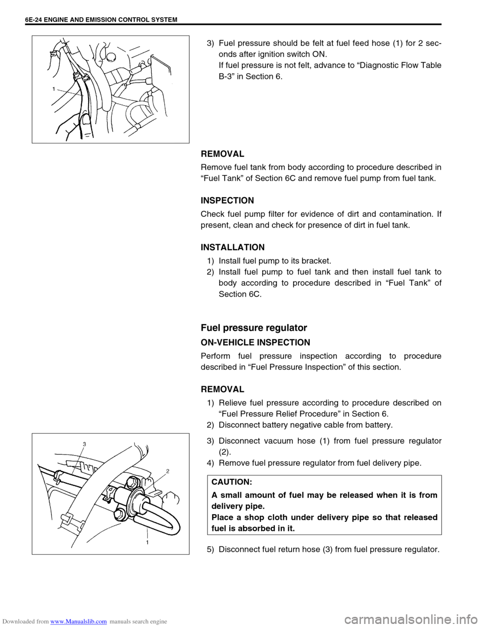
3) Fuel pressure should be felt at fuel feed hose (1) for 2 sec-
onds after ignition switch ON.
If fuel pressure is not felt, advance to “Diagnostic Flow Table
B-3” in Section 6.
REMOVAL
Remove fuel tank from body according to procedure described in
“Fuel Tank” of Section 6C and remove fuel pump from fuel tank.
INSPECTION
Check fuel pump filter for evidence of dirt and contamination. If
present, clean and check for presence of dirt in fuel tank.
INSTALLATION
1) Install fuel pump to its bracket.
2) Install fuel pump to fuel tank and then install fuel tank to
body according to procedure described in “Fuel Tank” of
Section 6C.
Fuel pressure regulator
ON-VEHICLE INSPECTION
Perform fuel pressure inspection according to procedure
described in “Fuel Pressure Inspection” of this section.
REMOVAL
1) Relieve fuel pressure according to procedure described on
“Fuel Pressure Relief Procedure” in Section 6.
2) Disconnect battery negative cable from battery.
3) Disconnect vacuum hose (1) from fuel pressure regulator
(2).
4) Remove fuel pressure regulator from fuel delivery pipe.
5) Disconnect fuel return hose (3) from fuel pressure regulator.
CAUTION:
A small amount of fuel may be released when it is from
delivery pipe.
Place a shop cloth under delivery pipe so that released
fuel is absorbed in it.