2005 SUZUKI JIMNY coolant temperature
[x] Cancel search: coolant temperaturePage 376 of 687

Downloaded from www.Manualslib.com manuals search engine ENGINE GENERAL INFORMATION AND DIAGNOSIS 6-19
Fail-safe table
When any of the following DTCs is detected, ECM enters fail-safe mode as long as malfunction continues to
exist but that mode is canceled when ECM detects normal condition after that.
DTC NO. DETECTED ITEM FAIL-SAFE OPERATION (SYMPTOM)
P0105
(No.11)Manifold absolute pressure sensor circuit
malfunctionECM uses value determined by throttle opening and
engine speed.
P0110
(No.18)Intake air temp. sensor circuit malfunctionECM controls actuators assuming that intake air tem-
perature is 20 °C (68 °F).
P0115
(No.19)Engine coolant temp. sensor circuit mal-
functionECM controls actuators assuming that engine coolant
temperature is 80 °C (176 °F).
P0120
(No.13)Throttle position sensor circuit malfunc-
tionECM controls actuators assuming that throttle opening
is 20°. (High idle speed)
P0335
(No.23)Crankshaft position sensor circuit mal-
functionECM controls injection system sequential injection to
synchronous injection. (Cranking for a few seconds to
start engine)
P0340
(No.15)Camshaft position sensor circuit malfunc-
tionECM controls injection system sequential injection to
synchronous injection. (Cranking for a few seconds to
start engine)
P0500
(No.16)Vehicle speed sensor malfunction ECM stops idle air control.
P1450Barometric pressure sensor low / high
inputECM controls actuators assuming that barometric
pressure is 100 kPa (760 mmHg).
P1570
(No.21)ABS signal circuit malfunctionECM controls actuators assuming that ABS signal is
OFF.
Page 387 of 687

Downloaded from www.Manualslib.com manuals search engine 6-30 ENGINE GENERAL INFORMATION AND DIAGNOSIS
Scan tool data definitions
FUEL SYSTEM (FUEL SYSTEM STATUS)
Air / fuel ratio feedback loop status displayed as either open or closed loop. Open indicates that ECM ignores
feedback from the exhaust oxygen sensor.
Closed indicates final injection duration is corrected for oxygen sensor feedback.
CALC LOAD (CALCULATED LOAD VALUE, %)
Engine load displayed as a percentage of maximum possible load. Value is calculated mathematically using the
formula : actual (current) intake air volume ÷ maximum possible intake air volume x 100%.
COOLANT TEMP. (ENGINE COOLANT TEMPERATURE, °C, °F)
It is detected by engine coolant temp. sensor
SHORT FT B1 (SHORT TERM FUEL TRIM, %)
Short term fuel trim value represents short term corrections to the air / fuel mixture computation. A value of 0
indicates no correction, a value greater than 0 means an enrichment correction, and a value less than 0 implies
an enleanment correction.
LONG FT B1 (LONG TERM FUEL TRIM, %)
Long term fuel trim Value represents long term corrections to the air / fuel mixture computation. A value of 0 indi-
cates no correction, a value greater than 0 means an enrichment correction, and a value less than 0 implies an
enleanment correction.
MAP (INTAKE MANIFOLD ABSOLUTE PRESSURE, kPa, inHg)
It is detected by manifold absolute pressure sensor and used (among other things) to compute engine load.
ENGINE SPEED (rpm)
It is computed by reference pulses from crankshaft position sensor.
VEHICLE SPEED (km/h, MPH)
It is computed based on pulse signals from vehicle speed sensor.
IGNITION ADVANCE (IGNITION TIMING ADVANCE FOR NO.1 CYLINDER, °)
Ignition timing of NO.1 cylinder is commanded by ECM. The actual ignition timing should be checked by using
the timing light.
INTAKE AIR TEMP. (°C, °F)
It is detected by intake air temp. sensor and used to determine the amount of air passing into the intake manifold
as air density varies with temperature.
MAF (MASS AIR FLOW RATE, gm/s, lb/min)
It represents total mass of air entering intake manifold which is computed based on signals from MAP sensor,
IAT sensor, TP sensor, etc.BRAKE SWIgnition switch
ONBrake pedal is depressing ON
Brake pedal is releasing OFF
BLOWER FANIgnition switch
ONBlower fan switch ON ON
Blower fan switch OFF OFF
A/C MAG CLUTCHIgnition switch
ONA/C operating ON
A/C not operating OFF SCAN TOOL DATA CONDITION REFERENCE VALUES
Page 410 of 687

Downloaded from www.Manualslib.com manuals search engine ENGINE GENERAL INFORMATION AND DIAGNOSIS 6-53
DTC P0115 (DTC No.19) Engine Coolant Temperature (ECT) Circuit Malfunc-
tion
CIRCUIT DESCRIPTION
DTC CONFIRMATION PROCEDURE
1) Clear DTC, start engine and keep it at idle for 1 min.
2) Select “DTC” mode on scan tool and check DTC.
DTC DETECTING CONDITION POSSIBLE CAUSE
Low engine coolant temperature (High voltage-High resis-
tance)
High engine coolant temperature (Low voltage-Low resis-
tance)“G/B” circuit open or shorted to power
“B/Bl” circuit open
ECT sensor malfunction
ECM malfunction
NOTE:
When DTC P0105 (No.11), P0110 (No.18), P0115 (No.19), P0120 (No.13) and P0460 are indicated
together, it is possible that “B/Bl” circuit is open.
Before inspecting, be sure to check that coolant temp. meter in combination meter indicates normal
operating temperature (Engine is not overheating).
When this DTC and P1709 are stored together, also clear DTC stored in TCM after completion of
repair.
Page 414 of 687

Downloaded from www.Manualslib.com manuals search engine ENGINE GENERAL INFORMATION AND DIAGNOSIS 6-57
DTC P0121 Throttle Position Circuit Range / Performance Problem
WIRING DIAGRAM
Refer to DTC P0120 section.
CIRCUIT DESCRIPTION
DTC CONFIRMATION PROCEDURE
1) Turn ignition switch OFF. Clear DTC with ignition switch ON, check vehicle and environmental condition for :
–Altitude (barometric pressure) : 2400 m, 8000 ft or less (560 mmHg, 75 kPa or more)
–Ambient temp. : –10 °C, 14 °F or higher
–Intake air temp. : 70 °C, 158 °F or lower
–Engine coolant temp. : 70 °C, 158 °F or higher
2) Warm up engine to normal operating temperature.
3) Increase vehicle speed to 30 – 40 mph, 50 – 60 km/h in 3rd gear or “D” range and hold throttle valve at that
opening position for 1 min.
4) Stop vehicle.
5) Check DTC in “DTC” mode and pending DTC in “ON BOARD TEST” or “PENDING DTC” mode.
INSPECTION
DTC DETECTING CONDITION POSSIBLE CAUSE
After engine warmed up.
Difference between actual throttle opening (detected from TP sensor)
and opening calculated by ECM (Obtained on the basis of engine
speed and intake manifold pressure) in larger than specified value.
✱2 driving cycle detection logic, continuous monitoringTP sensor malfunction
High resistance in the circuit
ECM malfunction
WARNING:
When performing a road test, select a place where there is no traffic or possibility of a traffic acci-
dent and be very careful during testing to avoid occurrence of an accident.
Road test should be carried out with 2 persons, a driver and a tester, on a level road.
Step Action Yes No
1Was “Engine Diag. Flow Table” performed? Go to Step 2. Go to “Engine Diag. Flow
Table”.
2 Is SUZUKI scan tool available? Go to Step 3. Go to Step 4.
3 Check TP Sensor and Its Circuit.
1) Turn ignition switch OFF and connect
SUZUKI scan tool to DLC. See Fig. 1.
2) Turn ignition switch ON and check TP sen-
sor output voltage when throttle valve is at
idle position and fully opened. See Fig. 3.
Dose voltage vary within specified value linearly
as shown in figure?Substitute a known-good
ECM and recheck.Go to Step 5.
Page 490 of 687

Downloaded from www.Manualslib.com manuals search engine ENGINE MECHANICAL (M13 ENGINE) 6A1-9
Valve Lash (Clearance)
1) Remove negative cable at battery.
2) Remove cylinder head cover referring to “Cylinder Head
Cover” in this section.
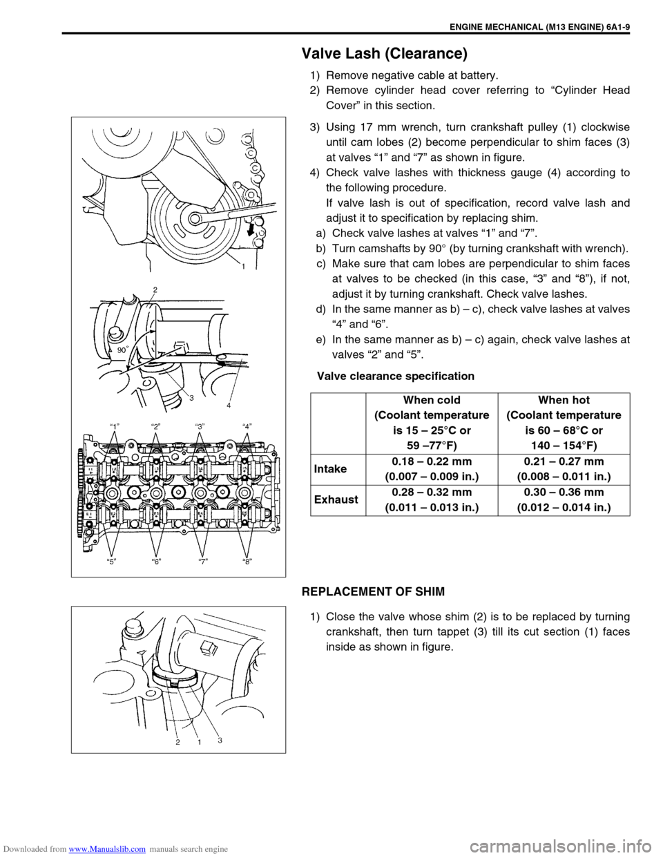
3) Using 17 mm wrench, turn crankshaft pulley (1) clockwise
until cam lobes (2) become perpendicular to shim faces (3)
at valves “1” and “7” as shown in figure.
4) Check valve lashes with thickness gauge (4) according to
the following procedure.
If valve lash is out of specification, record valve lash and
adjust it to specification by replacing shim.
a) Check valve lashes at valves “1” and “7”.
b) Turn camshafts by 90° (by turning crankshaft with wrench).
c) Make sure that cam lobes are perpendicular to shim faces
at valves to be checked (in this case, “3” and “8”), if not,
adjust it by turning crankshaft. Check valve lashes.
d) In the same manner as b) – c), check valve lashes at valves
“4” and “6”.
e) In the same manner as b) – c) again, check valve lashes at
valves “2” and “5”.
Valve clearance specification
REPLACEMENT OF SHIM
1) Close the valve whose shim (2) is to be replaced by turning
crankshaft, then turn tappet (3) till its cut section (1) faces
inside as shown in figure.When cold
(Coolant temperature
is 15 – 25°C or
59 –77°F)When hot
(Coolant temperature
is 60 – 68°C or
140 – 154°F)
Intake0.18 – 0.22 mm
(0.007 – 0.009 in.)0.21 – 0.27 mm
(0.008 – 0.011 in.)
Exhaust0.28 – 0.32 mm
(0.011 – 0.013 in.)0.30 – 0.36 mm
(0.012 – 0.014 in.)
Page 578 of 687

Downloaded from www.Manualslib.com manuals search engine ENGINE COOLING 6B-1
6B
SECTION 6B
ENGINE COOLING
CONTENTS
General Description ........................................6B-2
Cooling System Circulation ........................... 6B-2
Radiator Cap ................................................. 6B-3
Coolant Reservoir ......................................... 6B-3
Water Pump .................................................. 6B-4
Thermostat .................................................... 6B-4
Cooling Fan Clutch ........................................ 6B-4
Coolant (Water) Temperature Gauge............ 6B-4
Diagnosis .........................................................6B-5
Maintenance ....................................................6B-6
Coolant .......................................................... 6B-6
Coolant Level ................................................ 6B-7
Cooling System Service ................................ 6B-7Cooling System Flush and Refill ................... 6B-8
Water Pump Belt Tension ............................. 6B-9
On-Vehicle Service ....................................... 6B-10
Cooling System Component ....................... 6B-10
Coolant Draining ......................................... 6B-11
Cooling Water Pipes or Hoses .................... 6B-11
Thermostat .................................................. 6B-11
Water Pump Belt and Cooling Fan ............. 6B-13
Radiator ...................................................... 6B-14
Water Pump ................................................ 6B-15
Required Service Material ............................ 6B-17
Tightening Torque Specification ................. 6B-17
Page 580 of 687

Downloaded from www.Manualslib.com manuals search engine ENGINE COOLING 6B-3
Radiator Cap
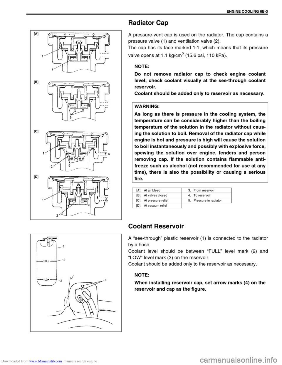
A pressure-vent cap is used on the radiator. The cap contains a
pressure valve (1) and ventilation valve (2).
The cap has its face marked 1.1, which means that its pressure
valve opens at 1.1 kg/cm
2 (15.6 psi, 110 kPa).
Coolant Reservoir
A “see-through” plastic reservoir (1) is connected to the radiator
by a hose.
Coolant level should be between “FULL” level mark (2) and
“LOW” level mark (3) on the reservoir.
Coolant should be added only to the reservoir as necessary.NOTE:
Do not remove radiator cap to check engine coolant
level; check coolant visually at the see-through coolant
reservoir.
Coolant should be added only to reservoir as necessary.
WARNING:
As long as there is pressure in the cooling system, the
temperature can be considerably higher than the boiling
temperature of the solution in the radiator without caus-
ing the solution to boil. Removal of the radiator cap while
engine is hot and pressure is high will cause the solution
to boil instantaneously and possibly with explosive force,
spewing the solution over engine, fenders and person
removing cap. If the solution contains flammable anti-
freeze such as alcohol (not recommended for use at any
time), there is also the possibility or causing a serious
fire.
[A]: At air bleed 3. From reservoir
[B]: At valves closed 4. To reservoir
[C]: At pressure relief 5. Pressure in radiator
[D]: At vacuum relief
NOTE:
When installing reservoir cap, set arrow marks (4) on the
reservoir and cap as the figure.
Page 581 of 687

Downloaded from www.Manualslib.com manuals search engine 6B-4 ENGINE COOLING
Water Pump
The centrifugal type water pump is used in the cooling system.
The pump impeller is supported by a totally sealed bearing.
The water pump can not be disassembled.
Thermostat
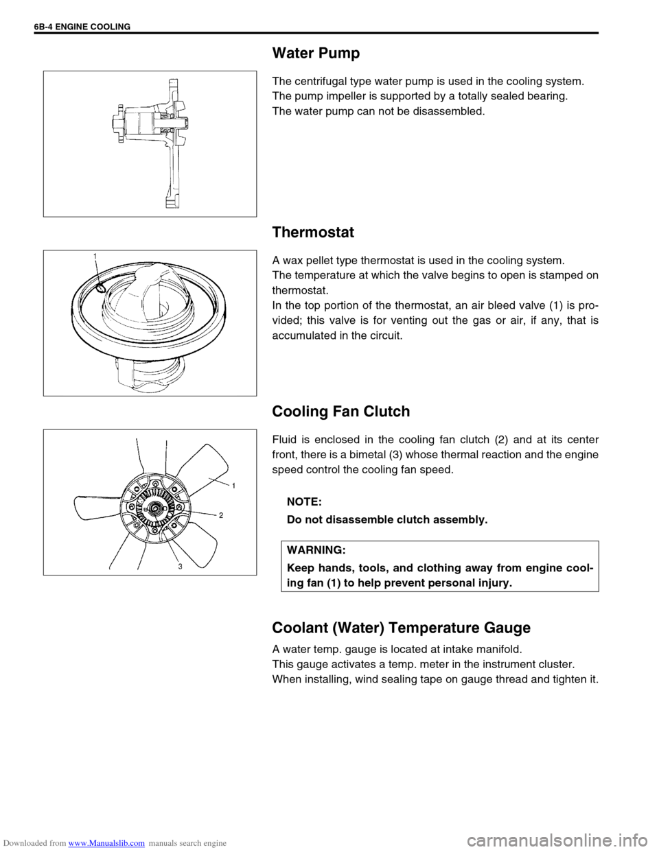
A wax pellet type thermostat is used in the cooling system.
The temperature at which the valve begins to open is stamped on
thermostat.
In the top portion of the thermostat, an air bleed valve (1) is pro-
vided; this valve is for venting out the gas or air, if any, that is
accumulated in the circuit.
Cooling Fan Clutch
Fluid is enclosed in the cooling fan clutch (2) and at its center
front, there is a bimetal (3) whose thermal reaction and the engine
speed control the cooling fan speed.
Coolant (Water) Temperature Gauge
A water temp. gauge is located at intake manifold.
This gauge activates a temp. meter in the instrument cluster.
When installing, wind sealing tape on gauge thread and tighten it.
NOTE:
Do not disassemble clutch assembly.
WARNING:
Keep hands, tools, and clothing away from engine cool-
ing fan (1) to help prevent personal injury.