2005 SUZUKI JIMNY air
[x] Cancel search: airPage 209 of 687

Downloaded from www.Manualslib.com manuals search engine 3D-36 FRONT SUSPENSION
Leading Arm / Bushing
REMOVAL
1) Hoist vehicle.
2) Remove air locking hub vacuum pipe clamp bolts (2) (for
4WD).
3) Support front axle housing by using floor jack.
4) Remove shock absorber lower mounting bolt, refer to “Front
Shock Absorber” in this section.
5) Remove mounting bolts and leading arm (1).
6) Remove bushings by using hydraulic press and special
tools.
Special tool
(A) : 09924-74510
(B) : 09951-16030
(C) : 09951-26010
1. Leading arm (right side)
Page 210 of 687

Downloaded from www.Manualslib.com manuals search engine FRONT SUSPENSION 3D-37
INSTALLATION
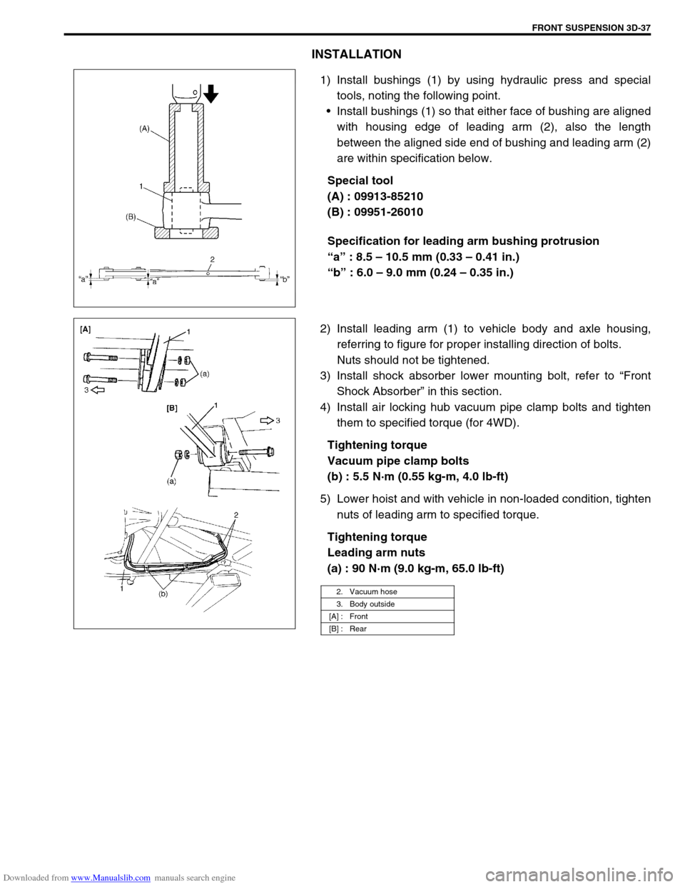
1) Install bushings (1) by using hydraulic press and special
tools, noting the following point.
Install bushings (1) so that either face of bushing are aligned
with housing edge of leading arm (2), also the length
between the aligned side end of bushing and leading arm (2)
are within specification below.
Special tool
(A) : 09913-85210
(B) : 09951-26010
Specification for leading arm bushing protrusion
“a” : 8.5 – 10.5 mm (0.33 – 0.41 in.)
“b” : 6.0 – 9.0 mm (0.24 – 0.35 in.)
2) Install leading arm (1) to vehicle body and axle housing,
referring to figure for proper installing direction of bolts.
Nuts should not be tightened.
3) Install shock absorber lower mounting bolt, refer to “Front
Shock Absorber” in this section.
4) Install air locking hub vacuum pipe clamp bolts and tighten
them to specified torque (for 4WD).
Tightening torque
Vacuum pipe clamp bolts
(b) : 5.5 N·m (0.55 kg-m, 4.0 lb-ft)
5) Lower hoist and with vehicle in non-loaded condition, tighten
nuts of leading arm to specified torque.
Tightening torque
Leading arm nuts
(a) : 90 N·m (9.0 kg-m, 65.0 lb-ft)
2. Vacuum hose
3. Body outside
[A] : Front
[B] : Rear
Page 212 of 687

Downloaded from www.Manualslib.com manuals search engine FRONT SUSPENSION 3D-39
9) Remove knuckle seal cover bolts, take off knuckle seal cover
(1), knuckle seal and knuckle seal retainer.
10) Remove upper and lower kingpins (2) from steering knuckle.
11) Remove knuckle with hub assembly from axle housing (for
2WD model) or draw out right and left axle shafts with
knuckle and hub assembly (for 4WD model).
12) Before removing front propeller shaft (1), give match marks
(3) on joint flange (2) and front propeller shaft as shown (for
4WD).
13) Remove front differential from front axle housing (for 4WD).
14) Remove air locking hub vacuum pipe from axle housing (1)
(for 4WD).
15) Support front axle housing by using floor jack.
16) Remove lateral rod, refer to “Lateral Rod” in this section.
17) Remove stabilizer bar, refer to “Stabilizer Bar / Bushings” in
this section.
18) Loosen mounting nuts of leading arm (1) but don’t remove
bolts. NOTE:
The removed upper and lower kingpins (2) must be kept
separated so as to prevent an error when putting them
back in their place in reassembly.
NOTE:
At this time, lower kingpin bearing sometimes falls off.
So remove bearing while pulling off knuckle gradually.
Page 214 of 687

Downloaded from www.Manualslib.com manuals search engine FRONT SUSPENSION 3D-41
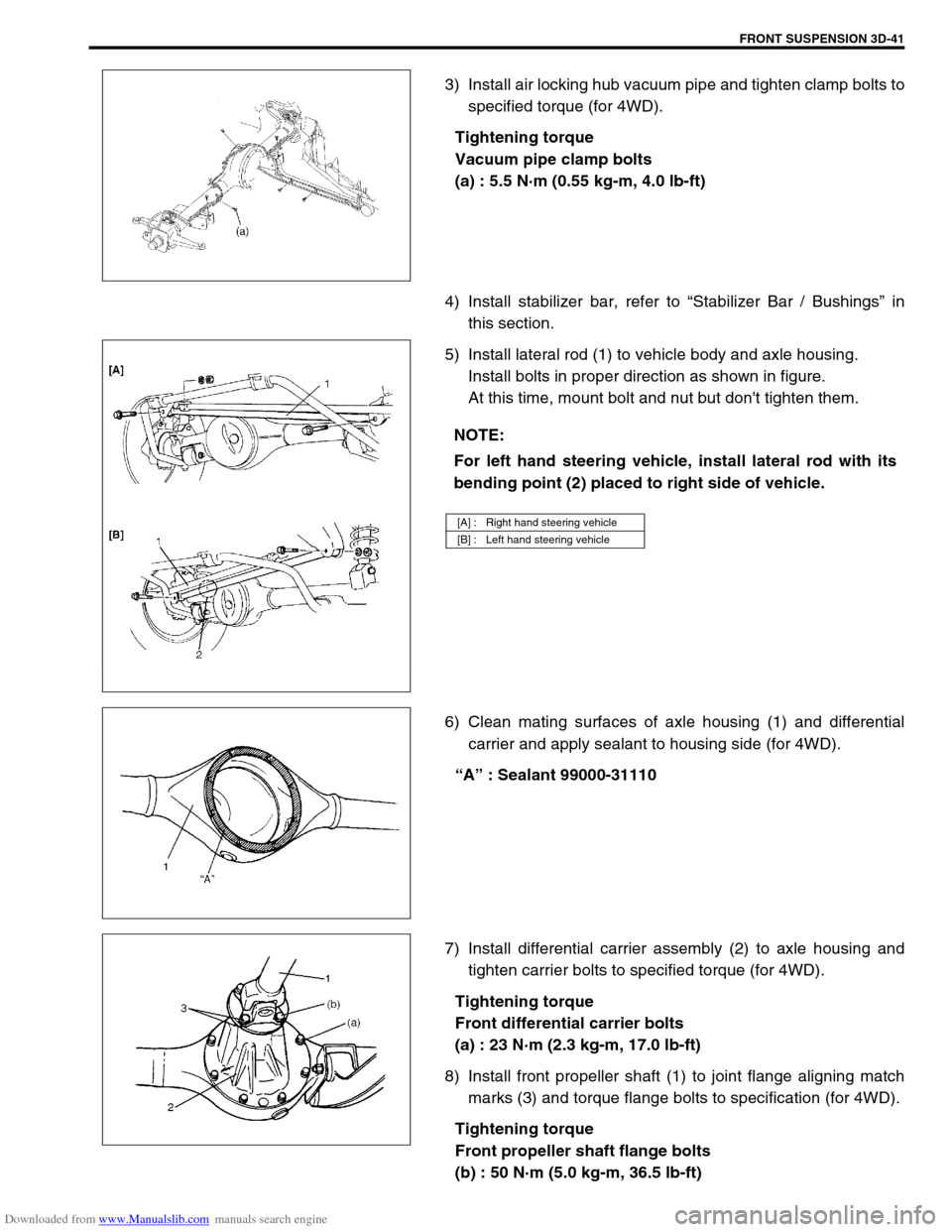
3) Install air locking hub vacuum pipe and tighten clamp bolts to
specified torque (for 4WD).
Tightening torque
Vacuum pipe clamp bolts
(a) : 5.5 N·m (0.55 kg-m, 4.0 lb-ft)
4) Install stabilizer bar, refer to “Stabilizer Bar / Bushings” in
this section.
5) Install lateral rod (1) to vehicle body and axle housing.
Install bolts in proper direction as shown in figure.
At this time, mount bolt and nut but don't tighten them.
6) Clean mating surfaces of axle housing (1) and differential
carrier and apply sealant to housing side (for 4WD).
“A” : Sealant 99000-31110
7) Install differential carrier assembly (2) to axle housing and
tighten carrier bolts to specified torque (for 4WD).
Tightening torque
Front differential carrier bolts
(a) : 23 N·m (2.3 kg-m, 17.0 lb-ft)
8) Install front propeller shaft (1) to joint flange aligning match
marks (3) and torque flange bolts to specification (for 4WD).
Tightening torque
Front propeller shaft flange bolts
(b) : 50 N·m (5.0 kg-m, 36.5 lb-ft)
NOTE:
For left hand steering vehicle, install lateral rod with its
bending point (2) placed to right side of vehicle.
[A] : Right hand steering vehicle
[B] : Left hand steering vehicle
Page 217 of 687

Downloaded from www.Manualslib.com manuals search engine 3D-44 FRONT SUSPENSION
Tightening Torque Specifications
Required Service Material
Fastening partTightening torque
Nm kg-m lb-ft
Stabilizer mount bracket bolt 20 2.0 14.5
Stabilizer ball joint nut 50 5.0 36.5
Shock absorber lock nut 29 2.9 21.0
Shock absorber lower nut 90 9.0 65.0
Brake caliper carrier bolt 85 8.5 61.5
Wheel bearing lock nut 220 22.0 160.0
Wheel bearing lock washer screw 1.5 0.15 1.0
Air locking hub bolt 48 4.8 35.0
Wheel spindle bolt 50 5.0 36.5
Kingpin bolt 25 2.5 18.0
Knuckle seal cover bolt 10 1.0 7.5
Tie-rod end nut
43 4.3 31.5
Drag-rod end nut (Knuckle side)
Lateral rod bolt and nut
90 9.0 65.0
Leading arm nut
Front differential carrier bolt 23 2.3 17.0
Front propeller shaft flange bolt 50 5.0 36.5
Wheel nut 95 9.5 69.0
Vacuum pipe clamp bolt 5.5 0.55 4.0
MaterialRecommended SUZUKI product
(Part Number)Use
Lithium grease SUZUKI SUPER GREASE (A)
(99000-25010)Knuckle seal / axle shaft oil seal
Recess of wheel spindles
Wheel hub oil seal
Wheel bearing
Spindle thrust washer
Spindle bush (inside and flange
part)
Spindle oil seal
SUZUKI SUPER GREASE (C)
(99000-25030)Kingpin bearing
Axle shaft joint (for 4WD)
Sealant SUZUKI BOND NO. 1215
(99000-31110)Mating surfaces of wheel spindle
and knuckle
Mating surface of differential carrier
and axle housing
Sealing compound SUZUKI SEALING COMPOUND
366E
(99000-31090)Mating surface of wheel spindle and
knuckle
Kingpin
Mating surfaces of hub cap and
wheel hub
Page 220 of 687

Downloaded from www.Manualslib.com manuals search engine REAR SUSPENSION 3E-1
6F1
6F2
6G
1A
6K
7A
7A1
7B1
3E
8A
8B
8A
8B
8C
8D
8E
9
10
10A
10B
SECTION 3E
REAR SUSPENSION
CONTENTS
General Description ....................................... 3E-2
Diagnosis ........................................................ 3E-3
Diagnosis Table ........................................... 3E-3
Rear Shock Absorber Check ........................ 3E-3
Trailing Arm, Lateral Rod, Axle Housing
and Coil Spring Check ................................. 3E-3
Trailing Arm and Lateral Rod Bush Check ... 3E-3
Rear Suspension Fasteners ......................... 3E-4
Bearing Retainer and Axle Shaft Oil Seal
Check ........................................................... 3E-4
Bump Stopper and Spring Rubber Seat
Check ........................................................... 3E-4
Wheel Disc, Nut and Bearing Check ............ 3E-4On-Vehicle Service ........................................ 3E-5
Rear Shock Absorber................................... 3E-5
Coil Spring ................................................... 3E-6
Bump Stopper .............................................. 3E-9
Lateral Rod .................................................. 3E-9
Trailing Arm / Bushing................................ 3E-10
Rear Axle Shaft and Wheel Bearing .......... 3E-12
Rear Axle Shaft Inner Oil Seal ................... 3E-17
Rear Axle Housing ..................................... 3E-18
Tightening Torque Specifications .............. 3E-22
Required Service Materials ......................... 3E-22
Special Tools ................................................ 3E-23
WARNING:
When hoisting vehicle, be sure to select the lifting point suitable for the service work referring to Sec-
tion 0A.
NOTE:
All suspension fasteners are an important attaching part in that it could affect the performance of
vital parts and systems, and/or could result in major repair expense. They must be replaced with
one of the same part number or with an equivalent part if replacement becomes necessary. Do not
use a replacement part of lesser quality or substitute design. Torque values must be used as speci-
fied during reassembly to assure proper retention of this part.
Never attempt to heat, quench or straighten any suspension part. Replace it with a new part, or
damage to the part may result.
Page 244 of 687

Downloaded from www.Manualslib.com manuals search engine WHEELS AND TIRES 3F-1
6F1
6F2
6G
3F
8A
8B
8C
8B
8C
8D
8E
9
10
10A
10B
SECTION 3F
WHEELS AND TIRES
CONTENTS
General Description ........................................ 3F-2
Tires .............................................................. 3F-2
Wheels .......................................................... 3F-2
Replacement Tires ........................................ 3F-2
Replacement Wheels ................................ 3F-3
How To Measure Wheel Runout ............... 3F-3
Metric Lug Nuts and Wheel Studs ............. 3F-3
Diagnosis ......................................................... 3F-4
Diagnosis Table ............................................ 3F-4
Balancing Wheels ......................................... 3F-4
General Balance Procedure .......................... 3F-4
Off-vehicle balancing ................................. 3F-4
On-vehicle balancing ................................. 3F-4
Maintenance and Minor Adjustments ........... 3F-6Wheel and Tire.............................................. 3F-6
Studs ......................................................... 3F-6
Matched tires and wheels
(For vehicle equipped with steel
wheels) ...................................................... 3F-6
Inflation of Tires ............................................ 3F-6
Tire placard ............................................... 3F-7
Tire rotation ............................................... 3F-7
On-Vehicle Service ......................................... 3F-8
Wheel ............................................................ 3F-8
Tire ................................................................ 3F-9
Mounting and demounting......................... 3F-9
Repair........................................................ 3F-9
NOTE:
All wheel fasteners are important attaching parts in that they could affect the performance of vital
parts and systems, and/or could result in major repair expense. They must be replaced with one of the
same part number or with an equivalent part if replacement becomes necessary. Do not use a replace-
ment part of lesser quality or substitute design. Torque values must be used as specified during reas-
sembly to assure proper retention of all parts.
There is to be no welding as it may result in extensive damage and weakening of the metal.
Page 245 of 687

Downloaded from www.Manualslib.com manuals search engine 3F-2 WHEELS AND TIRES
General Description
Tires
This vehicle is equipped with following tire.
Tire size
: 205/70 R15 or 175/80 R15
The tires are of tubeless type. The tires are designed to operate satisfactorily with loads up to the full rated load
capacity when inflated to the recommended inflation pressure.
Correct tire pressures and driving habits have an important influence on tire life Heavy cornering, excessively
rapid acceleration, and unnecessary sharp braking increase tire wear.
Wheels
Standard equipment wheels are following steel wheels.
15 x 5 1/2 JJ
Replacement Tires
When replacement is necessary, the original equipment type tire should be used. Refer to the Tire Placard.
Replacement tires should be of the same size, load range and construction as those originally on the vehicle.
Use of any other size or type tire may affect ride, handling, speedometer / odometer calibration, vehicle ground
clearance and tire or snow chain clearance to the body and chassis.
It is recommended that new tires be installed in pairs on the same axle. If necessary to replace only one tire, it
should be paired with the tire having the most tread, to equalize braking traction.
The metric term for tire inflation pressure is the kilopascal (kPa).
Tire pressures will usually be printed in both kPa and psi on the
Tire Placard. Metric tire gauges are available from tool suppliers.
The following chart, converts commonly used inflation pressures
from kPa to psi. WARNING:
Do not mix different types of tires on the same vehicle such as radial, bias and bias-belted tires except
in emergencies, because vehicle handling may be seriously affected and may result in loss of control.
kPa
kgf/cm2psi
160
180
200
220
240
260
280
300
320
3401.6
1.8
2.0
2.2
2.4
2.6
2.8
3.0
3.2
3.423
26
29
32
35
38
41
44
47
50