2005 SUZUKI JIMNY Section 7c
[x] Cancel search: Section 7cPage 244 of 687

Downloaded from www.Manualslib.com manuals search engine WHEELS AND TIRES 3F-1
6F1
6F2
6G
3F
8A
8B
8C
8B
8C
8D
8E
9
10
10A
10B
SECTION 3F
WHEELS AND TIRES
CONTENTS
General Description ........................................ 3F-2
Tires .............................................................. 3F-2
Wheels .......................................................... 3F-2
Replacement Tires ........................................ 3F-2
Replacement Wheels ................................ 3F-3
How To Measure Wheel Runout ............... 3F-3
Metric Lug Nuts and Wheel Studs ............. 3F-3
Diagnosis ......................................................... 3F-4
Diagnosis Table ............................................ 3F-4
Balancing Wheels ......................................... 3F-4
General Balance Procedure .......................... 3F-4
Off-vehicle balancing ................................. 3F-4
On-vehicle balancing ................................. 3F-4
Maintenance and Minor Adjustments ........... 3F-6Wheel and Tire.............................................. 3F-6
Studs ......................................................... 3F-6
Matched tires and wheels
(For vehicle equipped with steel
wheels) ...................................................... 3F-6
Inflation of Tires ............................................ 3F-6
Tire placard ............................................... 3F-7
Tire rotation ............................................... 3F-7
On-Vehicle Service ......................................... 3F-8
Wheel ............................................................ 3F-8
Tire ................................................................ 3F-9
Mounting and demounting......................... 3F-9
Repair........................................................ 3F-9
NOTE:
All wheel fasteners are important attaching parts in that they could affect the performance of vital
parts and systems, and/or could result in major repair expense. They must be replaced with one of the
same part number or with an equivalent part if replacement becomes necessary. Do not use a replace-
ment part of lesser quality or substitute design. Torque values must be used as specified during reas-
sembly to assure proper retention of all parts.
There is to be no welding as it may result in extensive damage and weakening of the metal.
Page 247 of 687

Downloaded from www.Manualslib.com manuals search engine 3F-4 WHEELS AND TIRES
Diagnosis
Diagnosis Table
Refer to “Diagnosis Table” in Section 3.
Balancing Wheels
There are two types of wheel and tire balance: static and
dynamic. Static balance, as shown in figure, is equal distribution
of weight around wheel. Wheels that are statically unbalanced
cause bouncing action called tramp. This condition will eventually
cause uneven tire wear.
Dynamic balance, as shown in left figure, is equal distribution of
weight on each side of wheel centerline so that when the tire
spins there is no tendency for the assembly to move from side to
side. Wheels that are dynamically unbalanced may cause
shimmy.
General Balance Procedure
Deposits of mud, etc. must be cleaned from inside of rim.
Tire should be inspected for any damage, then balanced according to equipment manufacturer’s recommenda-
tion.
Off-vehicle balancing
Most electronic off-vehicle balancers are more accurate than on-vehicle spin balancers. They are easy to use
and give a dynamic (two plane) balance. Although they do not correct for drum or disc unbalance as does on-
vehicle spin balancing, this is overcome by their accuracy, usually to within 1/8 ounce.
On-vehicle balancing
On-vehicle balancing methods vary with equipment and tool manufacturers. Be sure to follow each manufac-
turer’s instructions during balancing operation.
1. Heavy spot wheel tramp [A] : Before correction
2. Balance weights addition point [B] : Corrective weights
3. C/L of spindle
1. Heavy spot wheel shimmy [C] : Before correction
2. Balance weights addition point [D] : Corrective weights
3. C/L of spindle
WARNING:
Stones should be removed from tread in order to avoid operator injury during spin balancing and to
obtain good balance.
Page 249 of 687

Downloaded from www.Manualslib.com manuals search engine 3F-6 WHEELS AND TIRES
Maintenance and Minor Adjustments
Wheel and Tire
Wheel repairs that use welding, heating, or peening are not approved. All damaged wheels should be replaced.
Studs
If a broken stud is found, see Section 3E (rear) or Section 3D (front) for Note and Replacement procedure.
Matched tires and wheels
(For vehicle equipped with steel wheels)
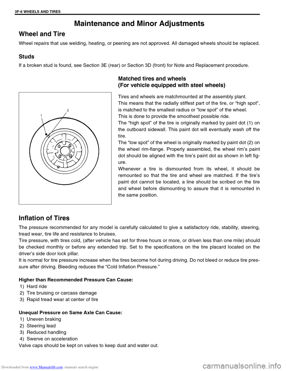
Tires and wheels are matchmounted at the assembly plant.
This means that the radially stiffest part of the tire, or “high spot”,
is matched to the smallest radius or “low spot” of the wheel.
This is done to provide the smoothest possible ride.
The “high spot” of the tire is originally marked by paint dot (1) on
the outboard sidewall. This paint dot will eventually wash off the
tire.
The “low spot” of the wheel is originally marked by paint dot (2) on
the wheel rim-flange. Properly assembled, the wheel rim’s paint
dot should be aligned with the tire’s paint dot as shown in left fig-
ure.
Whenever a tire is dismounted from its wheel, it should be
remounted so that the tire and wheel are matched. If the tire’s
paint dot cannot be located, a line should be scribed on the tire
and wheel before dismounting to assure that it is remounted in
the same position.
Inflation of Tires
The pressure recommended for any model is carefully calculated to give a satisfactory ride, stability, steering,
tread wear, tire life and resistance to bruises.
Tire pressure, with tires cold, (after vehicle has set for three hours or more, or driven less than one mile) should
be checked monthly or before any extended trip. Set to the specifications on the tire placard located on the
driver’s side door lock pillar.
It is normal for tire pressure increase when the tires become hot during driving. Do not bleed or reduce tire pres-
sure after driving. Bleeding reduces the “Cold Inflation Pressure.”
Higher than Recommended Pressure Can Cause:
1) Hard ride
2) Tire bruising or carcass damage
3) Rapid tread wear at center of tire
Unequal Pressure on Same Axle Can Cause:
1) Uneven braking
2) Steering lead
3) Reduced handling
4) Swerve on acceleration
Valve caps should be kept on valves to keep dust and water out.
Page 254 of 687

Downloaded from www.Manualslib.com manuals search engine PROPELLER SHAFTS 4B-1
6F1
6F2
6G
6H
6K
7A
7A1
7B1
7C1
7D
4B
8D
8E
9
8E
9
10
10A
10B
SECTION 4B
PROPELLER SHAFTS
CONTENTS
General Description ....................................... 4B-2
Components ................................................. 4B-2
Diagnosis ........................................................ 4B-2
Diagnosis Table ........................................... 4B-2
Propeller Shaft Joint Check .......................... 4B-2
On-Vehicle Service......................................... 4B-3Propeller Shafts ........................................... 4B-3
Universal Joint ............................................. 4B-5
Tightening Torque Specification .................. 4B-7
Required Service Material ............................. 4B-7
Special Tool .................................................... 4B-8
NOTE:
All propeller shaft fasteners are an important attaching part in that it could affect the performance
of vital parts and systems, and/or could result in major repair expense. They must be replaced with
one of the same part number or with an equivalent part if replacement becomes necessary. Do not
use a replacement part of lesser quality or substitute design. Torque values must be used as speci-
fied during reassembly to assure proper retention of this part.
Never attempt to heat, quench or straighten any propeller shaft part. Replace it with a new part, or
damage to the part may result.
Page 262 of 687

Downloaded from www.Manualslib.com manuals search engine BRAKES 5-1
6F1
6F2
6G
6H
6K
7A
7A1
7B1
7C1
7D
7E
5
9
10
10A
10B
9
10
10A
10B
SECTION 5
BRAKES
CONTENTS
General Description ......................................... 5-3
Diagnosis .......................................................... 5-4
Road Testing Brakes ...................................... 5-4
Brake Fluid Leaks .......................................... 5-4
Substandard or Contaminated Brake Fluid .... 5-4
Diagnosis Table ............................................. 5-5
Brake Pedal Free Height Adjustment ............. 5-8
Brake Pedal Play Check ................................ 5-8
Stop Light Switch Adjustment ........................ 5-8
Excessive Pedal Travel Check ....................... 5-9
Front Brake Disc Check ................................. 5-9
Front Brake Pad Check .................................. 5-9
Rear Brake Shoe Check .............................. 5-10
Master Cylinder and Brake Fluid Level
Check ........................................................... 5-10
Rear Drum Brake Shoe Adjustment ............. 5-11
Parking Brake Inspection and Adjustment ... 5-11
Booster Operation Check ............................. 5-12Fluid Pressure Test
(If Equipped with LSPV) ............................... 5-15
On-Vehicle Service ........................................ 5-17
Air Bleeding of Brake System ...................... 5-17
Brake Hose and Pipe Inspection.................. 5-18
Front Disc Brake .......................................... 5-19
Brake pad ................................................. 5-20
Caliper assembly...................................... 5-22
Brake Disc.................................................... 5-26
Rear Brake ................................................... 5-29
Brake drum............................................... 5-29
Brake shoe ............................................... 5-32
Wheel Cylinder............................................. 5-33
Brake back plate ...................................... 5-34
Master Cylinder .............................................. 5-36
Master Cylinder Reservoir ........................... 5-36
Master Cylinder Assembly ........................... 5-37 WARNING:
For lifting point of vehicle, refer to Section 0A.
WARNING:
For vehicles equipped with Supplement Restraint (Air Bag) System:
Service on and around the air bag system components or wiring must be performed only by an
authorized SUZUKI dealer. Refer to “Air Bag System Components and Wiring Location View” under
“General Description” in air bag system section in order to confirm whether you are performing ser-
vice on or near the air bag system components or wiring. Please observe all WARNINGS and “Ser-
vice Precautions” under “On-Vehicle Service” in air bag system section before performing service
on or around the air bag system components or wiring. Failure to follow WARNINGS could result in
unintentional activation of the system or could render the system inoperative. Either of these two
conditions may result in severe injury.
Technical service work must be started at least 90 seconds after the ignition switch is turned to the
“LOCK” position and the negative cable is disconnected from the battery. Otherwise, the system
may be activated by reserve energy in the Sensing and Diagnostic Module (SDM).
NOTE:
When inspecting and servicing vehicle equipped with ABS, be sure to refer to section 5E first.
All brake fasteners are important attaching parts in that they could affect the performance of vital
parts and systems, and/or could result in major repair expense. They must be replaced with one of
same part number or with an equivalent part if replacement becomes necessary. Do not use a
replacement part of lesser quality or substitute design. Torque values must be used as specified
during reassembly to assure proper retention of all parts. There is to be no welding as it may result
in extensive damage and weakening of the metal.
Page 268 of 687

Downloaded from www.Manualslib.com manuals search engine BRAKES 5-7
Brake warning light
turns on when brake
is appliedBrake fluid leaking from brake line Investigate leaky point, correct it
and add brake fluid.
Insufficient amount of brake fluid Add brake fluid.
Faulty P & Differential valve (Differential switch) Replace.
Brake warning light
fails to turn on even
when parking brake is
appliedBulb burnt out Replace bulb.
Brake warning light circuit open Repair circuit.
ABS warning light
does not turn on for 2
sec. after ignition
switch has turned ON.Bulb burnt out Replace bulb.
ABS warning light circuit open, if equipped with
ABS (including check relay)Check system referring to “TABLE-
A” in Section 5E.
ABS warning light
remains on after igni-
tion switch has turned
on for 2 sec.Malfunctioning ABS, if equipped with ABS Check system referring to “TABLE-
B” in Section 5E. Condition Possible Cause Correction
Page 269 of 687

Downloaded from www.Manualslib.com manuals search engine 5-8 BRAKES
Brake Pedal Free Height Adjustment
1) Check brake pedal free height.
If it is not within specification, check and adjust following item
2) and 3).
Brake pedal free height “a” from wall
LH steering vehicle : 221 – 227 mm (8.70 – 8.94 in.)
RH steering vehicle : 217 – 223 mm (8.54 – 8.78 in.)
2) Check measurement between booster mounting surface and
center of clevis pin hole. When booster push rod clevis has
been reinstalled, it is important that the measurement is
adjusted. (Refer to “Brake Booster Inspection and Adjust-
ment” in this section.)
3) Check stop light switch position. Adjust it if it is out of specifi-
cation.
Brake Pedal Play Check
Pedal play should be within specification below.
If out of specification, check stop light switch for proper installation
position and adjust if necessary.
Also check pedal shaft bolt and master cylinder pin installation for
looseness and replace if defective.
Brake pedal play “a” : 1 – 8 mm (0.04 – 0.31 in.)
Stop Light Switch Adjustment
Adjustment should be made as follows when installing switch. Pull
up brake pedal toward you and while holding it there, adjust
switch position so that clearance between end of thread and
brake pedal is specified. Then tighten lock nut to specified torque.
Clearance between brake pedal and stop light switch
“c” : 1.5 – 2.0 mm (0.06 – 0.08 in.)
Tightening torque
Stop light switch lock nut
(a) : 6.5 N·m (0.65 kg-m, 4.7 lb-ft)
Page 270 of 687

Downloaded from www.Manualslib.com manuals search engine BRAKES 5-9
Excessive Pedal Travel Check
1) Start engine.
2) Depress brake pedal a few times.
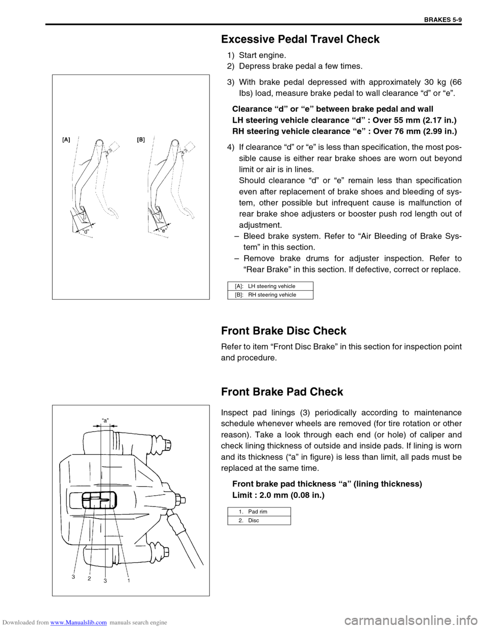
3) With brake pedal depressed with approximately 30 kg (66
Ibs) load, measure brake pedal to wall clearance “d” or “e”.
Clearance “d” or “e” between brake pedal and wall
LH steering vehicle clearance “d” : Over 55 mm (2.17 in.)
RH steering vehicle clearance “e” : Over 76 mm (2.99 in.)
4) If clearance “d” or “e” is less than specification, the most pos-
sible cause is either rear brake shoes are worn out beyond
limit or air is in lines.
Should clearance “d” or “e” remain less than specification
even after replacement of brake shoes and bleeding of sys-
tem, other possible but infrequent cause is malfunction of
rear brake shoe adjusters or booster push rod length out of
adjustment.
–Bleed brake system. Refer to “Air Bleeding of Brake Sys-
tem” in this section.
–Remove brake drums for adjuster inspection. Refer to
“Rear Brake” in this section. If defective, correct or replace.
Front Brake Disc Check
Refer to item “Front Disc Brake” in this section for inspection point
and procedure.
Front Brake Pad Check
Inspect pad linings (3) periodically according to maintenance
schedule whenever wheels are removed (for tire rotation or other
reason). Take a look through each end (or hole) of caliper and
check lining thickness of outside and inside pads. If lining is worn
and its thickness (“a” in figure) is less than limit, all pads must be
replaced at the same time.
Front brake pad thickness “a” (lining thickness)
Limit : 2.0 mm (0.08 in.)
[A]: LH steering vehicle
[B]: RH steering vehicle
1. Pad rim
2. Disc