Page 194 of 687

Downloaded from www.Manualslib.com manuals search engine FRONT SUSPENSION 3D-21
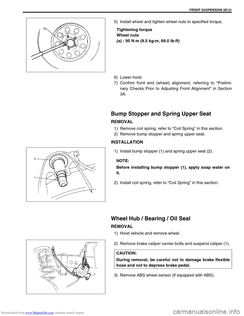
5) Install wheel and tighten wheel nuts to specified torque.
Tightening torque
Wheel nuts
(a) : 95 N·m (9.5 kg-m, 69.0 lb-ft)
6) Lower hoist.
7) Confirm front end (wheel) alignment, referring to “Prelimi-
nary Checks Prior to Adjusting Front Alignment” in Section
3A.
Bump Stopper and Spring Upper Seat
REMOVAL
1) Remove coil spring, refer to “Coil Spring” in this section.
2) Remove bump stopper and spring upper seat.
INSTALLATION
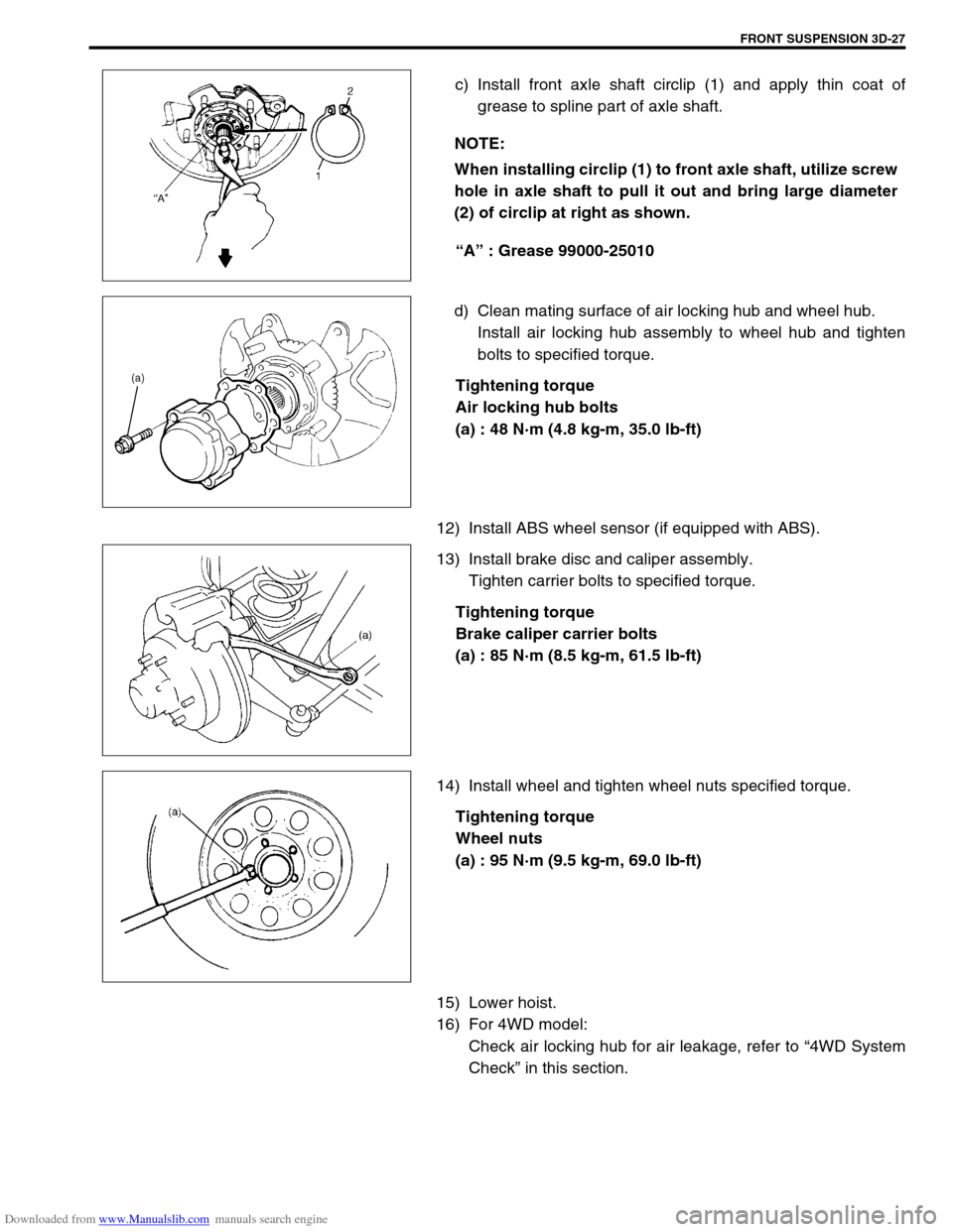
1) Install bump stopper (1) and spring upper seat (2).
2) Install coil spring, refer to “Coil Spring” in this section.
Wheel Hub / Bearing / Oil Seal
REMOVAL
1) Hoist vehicle and remove wheel.
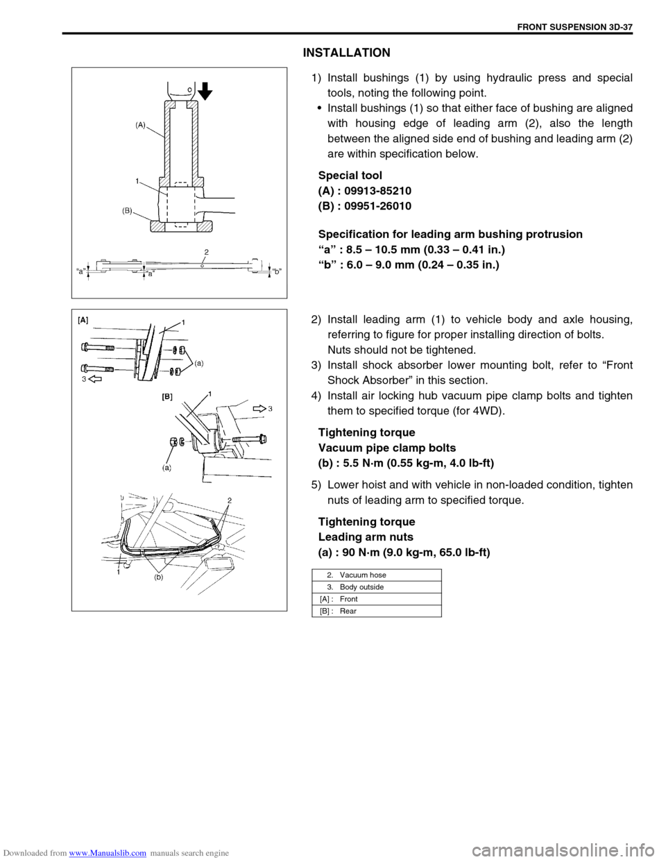
2) Remove brake caliper carrier bolts and suspend caliper (1).
3) Remove ABS wheel sensor (if equipped with ABS).
NOTE:
Before installing bump stopper (1), apply soap water on
it.
CAUTION:
During removal, be careful not to damage brake flexible
hose and not to depress brake pedal.
Page 200 of 687

Downloaded from www.Manualslib.com manuals search engine FRONT SUSPENSION 3D-27
c) Install front axle shaft circlip (1) and apply thin coat of
grease to spline part of axle shaft.
“A” : Grease 99000-25010
d) Clean mating surface of air locking hub and wheel hub.
Install air locking hub assembly to wheel hub and tighten
bolts to specified torque.
Tightening torque
Air locking hub bolts
(a) : 48 N·m (4.8 kg-m, 35.0 lb-ft)
12) Install ABS wheel sensor (if equipped with ABS).
13) Install brake disc and caliper assembly.
Tighten carrier bolts to specified torque.
Tightening torque
Brake caliper carrier bolts
(a) : 85 N·m (8.5 kg-m, 61.5 lb-ft)
14) Install wheel and tighten wheel nuts specified torque.
Tightening torque
Wheel nuts
(a) : 95 N·m (9.5 kg-m, 69.0 lb-ft)
15) Lower hoist.
16) For 4WD model:
Check air locking hub for air leakage, refer to “4WD System
Check” in this section. NOTE:
When installing circlip (1) to front axle shaft, utilize screw
hole in axle shaft to pull it out and bring large diameter
(2) of circlip at right as shown.
Page 201 of 687
Downloaded from www.Manualslib.com manuals search engine 3D-28 FRONT SUSPENSION
Steering Knuckle / Wheel Spindle
REMOVAL
1) Hoist vehicle and remove wheel.
2) Remove wheel hub assembly, refer to “Wheel Hub / Bearing /
Oil Seal” in this section.
3) Disconnect spindle vacuum hoses (1) from wheel spindle (for
4WD).
4) Remove disc dust cover (1) and wheel spindle (2).
5) Remove tie rod end (and drag rod end) nut(s) and discon-
nect tie rod end (and drag rod end) (2) from steering knuckle
(1) with special tool.
Special tool
(A) : 09913-65210
6) Remove knuckle seal cover bolts. Then remove knuckle seal
cover (1), knuckle seal and knuckle seal retainer from
knuckle. CAUTION:
Give match mark to each spindle vacuum hoses before
removing hose.
Page 203 of 687

Downloaded from www.Manualslib.com manuals search engine 3D-30 FRONT SUSPENSION
INSTALLATION
1) Set knuckle seal cover (2), knuckle seal (4) and knuckle seal
retainer (5) on front axle housing (6).
2) Apply grease within the knuckle (1). Amount of grease to be
applied within the knuckle (1) is approximately 100 g (for
4WD).
“A” : Grease 99000-25030
3) Apply grease to kingpin bearings (3) and install them to front
axle housing (6).
“A” : Grease 99000-25030
4) Apply sealant to indicated part of kingpin (1).
“A” : Sealant 99000-31090
5) Install steering knuckle (1) and king pins (2) and tighten king-
pin bolts to specified torque.
Tightening torque
Kingpin bolts
(a) : 25 N·m (2.5 kg-m, 18.0 lb-ft)
6) Apply grease to all around of knuckle seal lip.
“A” : Grease 99000-25010
7) Install knuckle seal retainer (1), knuckle seal (2) and knuckle
seal cover (3), tighten bolts to specified torque.
Tightening torque
Knuckle seal cover bolts
(a) : 10 N·m (1.0 kg-m, 7.5 lb-ft) NOTE:
When reusing bearing (3), install bearing (3) with sealing
at the top.
NOTE:
Install knuckle seal cover (3) and knuckle seal retainer (1)
so that their split section comes at the top as shown in
figure.
4. Steering knuckle 5. Split part
Page 205 of 687

Downloaded from www.Manualslib.com manuals search engine 3D-32 FRONT SUSPENSION
14) Blow air into pipes at the top and the front of wheel spindle
and check that it comes out of the hole as shown in figure
(for 4WD).
15) Connect spindle vacuum hoses to wheel spindle (for 4WD).
16) Connect tie rod and drag rod to steering knuckle, refer to
“Tie rod and Drag Rod” in Section 3B.
17) Install wheel hub assembly, refer to “Wheel Hub / Bearing /
Oil Seal” in this section.
18) Install wheel and tighten wheel nuts to specified torque.
Tightening torque
Wheel nuts
: 95 N·m (9.5 kg-m, 69.0 lb-ft)
19) Lower hoist.
Front Axle Shaft / Oil Seal / Kingpin Bearing
Outer Race
REMOVAL
1) Hoist vehicle.
2) Drain differential gear oil from front axle housing by loosing
drain plug (for 4WD).
3) Remove steering knuckle. For details, refer to “Steering
Knuckle / Wheel Spindle” in this section.
4) Draw out axle shaft (2).CAUTION:
As this hole is a part of the passage of the vacuum that
activates the air locking hub, if it is clogged with grease,
the air locking hub cannot be locked or unlocked.
Therefore, be careful not to apply too much grease to
avoid clogging the vacuum passage.
1. Front axle housing
Page 207 of 687
Downloaded from www.Manualslib.com manuals search engine 3D-34 FRONT SUSPENSION
4) Install axle shaft (2) to front axle housing (1) (for 4WD).
5) Install knuckle to front axle housing. For details, refer to
“Steering Knuckle / Wheel Spindle” in this section.
6) Refill front axle (differential) housing with new specified gear
oil (for 4WD). Refer to “Maintenance Service” in Section 7E
for refill.
7) After servicing, check that no oil leakage exists.
Steering Knuckle Seal
REMOVAL
1) Hoist vehicle.
2) Remove knuckle seal cover bolts and seal cover (1).
3) Cut oil seal in place with scissors or knife, and take it off.
INSTALLATION
1) Cut replacement oil seal at one place with scissors or a
knife.
Page 209 of 687
Downloaded from www.Manualslib.com manuals search engine 3D-36 FRONT SUSPENSION
Leading Arm / Bushing
REMOVAL
1) Hoist vehicle.
2) Remove air locking hub vacuum pipe clamp bolts (2) (for
4WD).
3) Support front axle housing by using floor jack.
4) Remove shock absorber lower mounting bolt, refer to “Front
Shock Absorber” in this section.
5) Remove mounting bolts and leading arm (1).
6) Remove bushings by using hydraulic press and special
tools.
Special tool
(A) : 09924-74510
(B) : 09951-16030
(C) : 09951-26010
1. Leading arm (right side)
Page 210 of 687

Downloaded from www.Manualslib.com manuals search engine FRONT SUSPENSION 3D-37
INSTALLATION
1) Install bushings (1) by using hydraulic press and special
tools, noting the following point.
Install bushings (1) so that either face of bushing are aligned
with housing edge of leading arm (2), also the length
between the aligned side end of bushing and leading arm (2)
are within specification below.
Special tool
(A) : 09913-85210
(B) : 09951-26010
Specification for leading arm bushing protrusion
“a” : 8.5 – 10.5 mm (0.33 – 0.41 in.)
“b” : 6.0 – 9.0 mm (0.24 – 0.35 in.)
2) Install leading arm (1) to vehicle body and axle housing,
referring to figure for proper installing direction of bolts.
Nuts should not be tightened.
3) Install shock absorber lower mounting bolt, refer to “Front
Shock Absorber” in this section.
4) Install air locking hub vacuum pipe clamp bolts and tighten
them to specified torque (for 4WD).
Tightening torque
Vacuum pipe clamp bolts
(b) : 5.5 N·m (0.55 kg-m, 4.0 lb-ft)
5) Lower hoist and with vehicle in non-loaded condition, tighten
nuts of leading arm to specified torque.
Tightening torque
Leading arm nuts
(a) : 90 N·m (9.0 kg-m, 65.0 lb-ft)
2. Vacuum hose
3. Body outside
[A] : Front
[B] : Rear