Page 183 of 687
Downloaded from www.Manualslib.com manuals search engine 3D-10 FRONT SUSPENSION
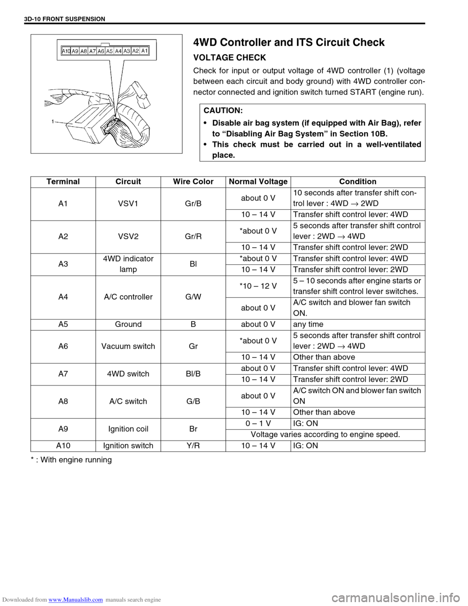
4WD Controller and ITS Circuit Check
VOLTAGE CHECK
Check for input or output voltage of 4WD controller (1) (voltage
between each circuit and body ground) with 4WD controller con-
nector connected and ignition switch turned START (engine run).
* : With engine runningCAUTION:
Disable air bag system (if equipped with Air Bag), refer
to “Disabling Air Bag System” in Section 10B.
This check must be carried out in a well-ventilated
place.
Terminal Circuit Wire Color Normal Voltage Condition
A1 VSV1 Gr/Babout 0 V10 seconds after transfer shift con-
trol lever : 4WD → 2WD
10 – 14 V Transfer shift control lever: 4WD
A2 VSV2 Gr/R*about 0 V5 seconds after transfer shift control
lever : 2WD → 4WD
10 – 14 V Transfer shift control lever: 2WD
A34WD indicator
lampBl*about 0 V Transfer shift control lever: 4WD
10 – 14 V Transfer shift control lever: 2WD
A4 A/C controller G/W*10 – 12 V5 – 10 seconds after engine starts or
transfer shift control lever switches.
about 0 VA/C switch and blower fan switch
ON.
A5 Ground B about 0 V any time
A6 Vacuum switch Gr*about 0 V5 seconds after transfer shift control
lever : 2WD → 4WD
10 – 14 V Other than above
A7 4WD switch Bl/Babout 0 V Transfer shift control lever: 4WD
10 – 14 V Transfer shift control lever: 2WD
A8 A/C switch G/Babout 0 VA/C switch ON and blower fan switch
ON
10 – 14 V Other than above
A9 Ignition coil Br0 – 1 V IG: ON
Voltage varies according to engine speed.
A10 Ignition switch Y/R 10 – 14 V IG: ON
Page 184 of 687
Downloaded from www.Manualslib.com manuals search engine FRONT SUSPENSION 3D-11
4WD Control System Check
AIR LOCKING HUB
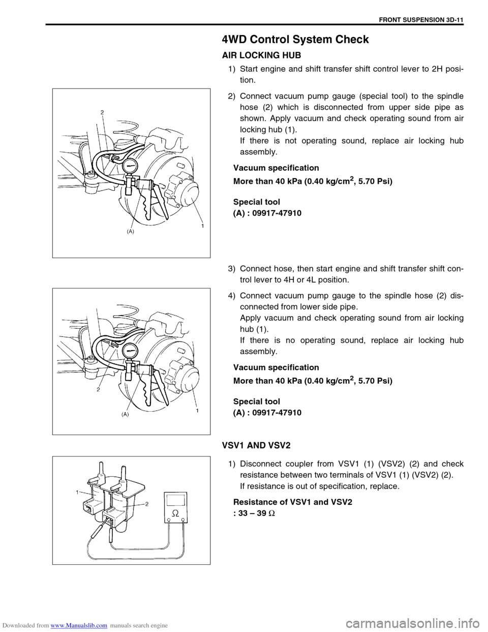
1) Start engine and shift transfer shift control lever to 2H posi-
tion.
2) Connect vacuum pump gauge (special tool) to the spindle
hose (2) which is disconnected from upper side pipe as
shown. Apply vacuum and check operating sound from air
locking hub (1).
If there is not operating sound, replace air locking hub
assembly.
Vacuum specification
More than 40 kPa (0.40 kg/cm
2, 5.70 Psi)
Special tool
(A) : 09917-47910
3) Connect hose, then start engine and shift transfer shift con-
trol lever to 4H or 4L position.
4) Connect vacuum pump gauge to the spindle hose (2) dis-
connected from lower side pipe.
Apply vacuum and check operating sound from air locking
hub (1).
If there is no operating sound, replace air locking hub
assembly.
Vacuum specification
More than 40 kPa (0.40 kg/cm
2, 5.70 Psi)
Special tool
(A) : 09917-47910
VSV1 AND VSV2
1) Disconnect coupler from VSV1 (1) (VSV2) (2) and check
resistance between two terminals of VSV1 (1) (VSV2) (2).
If resistance is out of specification, replace.
Resistance of VSV1 and VSV2
: 33 – 39
Ω
Page 185 of 687
Downloaded from www.Manualslib.com manuals search engine 3D-12 FRONT SUSPENSION
2) Blow air from B and check that air comes out of C.
If found faulty, replace.
3) Connect 12 V-battery to VSV1 (VSV2) terminals and check
continuity between A and B.
Blow air from B and check that air comes out of A.
If found faulty, replace.
VACUUM SWITCH
1) Disconnect coupler from vacuum switch and check resis-
tance between two terminals of vacuum switch.
If resistance is out of specification, replace.
Resistance of vacuum switch
: More than 1 M
Ω
2) Connect vacuum pump gauge and apply vacuum more than
40 kPa (0.40 kg/cm
2, 5.70 Psi), then check resistance
between terminals of vacuum switch.
If resistance is out of specification, replace.
Vacuum switch resistance
: Less than 0.8
Ω
Special tool
(A) : 09917-47910
4WD SWITCH
Refer to “4WD Switch” in Section 7D.
VACUUM HOSE / PIPE
Inspect vacuum hoses for leaks or cracks, vacuum pipes for
cracks, dents or corrosion. If defective, replace.
Page 186 of 687
Downloaded from www.Manualslib.com manuals search engine FRONT SUSPENSION 3D-13
CHECK VALVE
1) Remove check valve (1).
2) Close B side of check valve with finger as shown and apply
–50 cmHg vacuum by means of vacuum pump. Then check
that vacuum is applied. Apply vacuum to another side of
check valve and check that vacuum is not applied.
Replace if defective.
Special tool
(A) : 09917-47910
Stabilizer bar / bushing check
BAR
Inspect for damage or deformation. If defective, replace.
BUSHING
Inspect for damage, wear or deterioration. If defective, replace.
A : Intake manifold side
B : Vacuum switching valve side
Page 187 of 687
Downloaded from www.Manualslib.com manuals search engine 3D-14 FRONT SUSPENSION
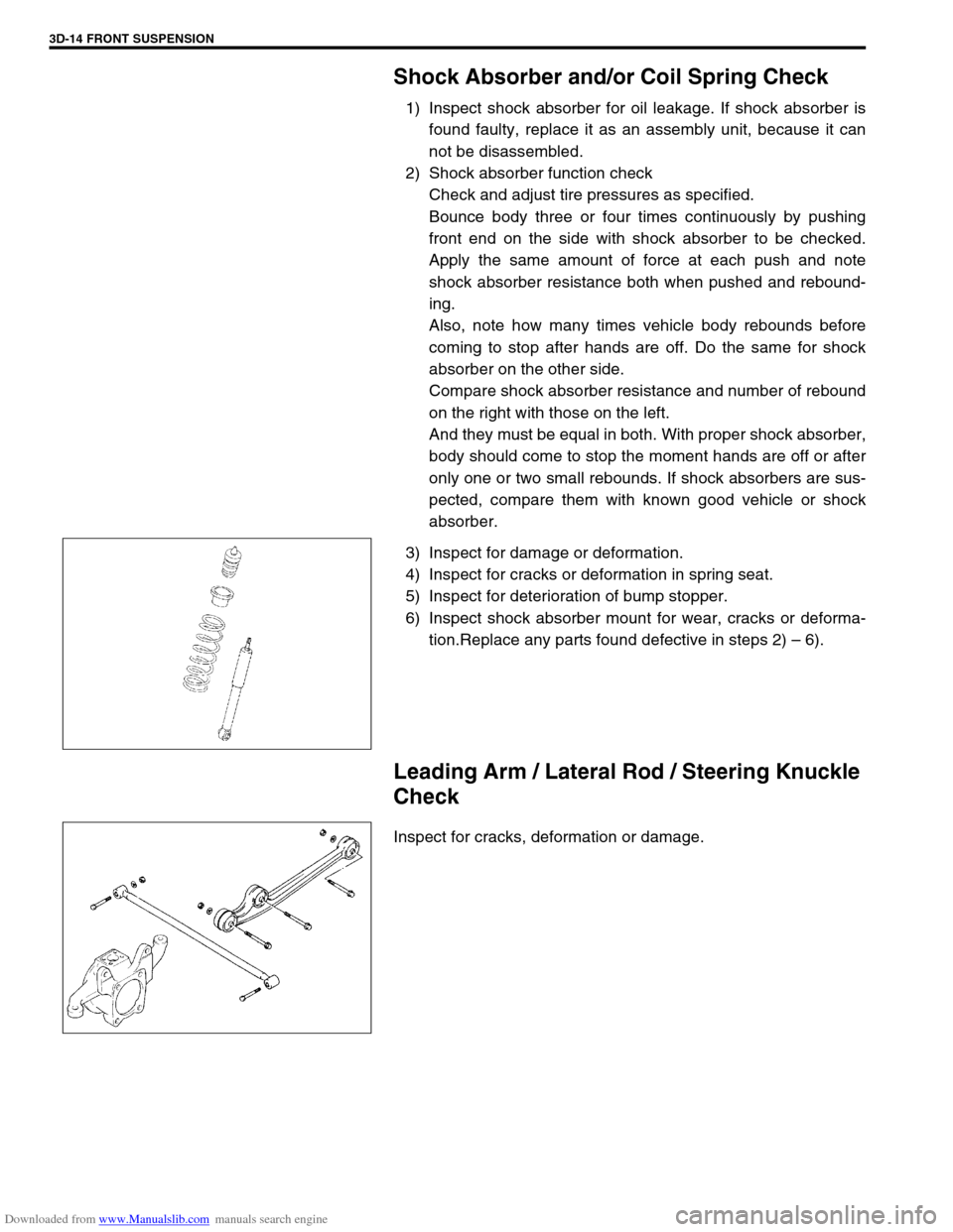
Shock Absorber and/or Coil Spring Check
1) Inspect shock absorber for oil leakage. If shock absorber is
found faulty, replace it as an assembly unit, because it can
not be disassembled.
2) Shock absorber function check
Check and adjust tire pressures as specified.
Bounce body three or four times continuously by pushing
front end on the side with shock absorber to be checked.
Apply the same amount of force at each push and note
shock absorber resistance both when pushed and rebound-
ing.
Also, note how many times vehicle body rebounds before
coming to stop after hands are off. Do the same for shock
absorber on the other side.
Compare shock absorber resistance and number of rebound
on the right with those on the left.
And they must be equal in both. With proper shock absorber,
body should come to stop the moment hands are off or after
only one or two small rebounds. If shock absorbers are sus-
pected, compare them with known good vehicle or shock
absorber.
3) Inspect for damage or deformation.
4) Inspect for cracks or deformation in spring seat.
5) Inspect for deterioration of bump stopper.
6) Inspect shock absorber mount for wear, cracks or deforma-
tion.Replace any parts found defective in steps 2) – 6).
Leading Arm / Lateral Rod / Steering Knuckle
Check
Inspect for cracks, deformation or damage.
Page 188 of 687
Downloaded from www.Manualslib.com manuals search engine FRONT SUSPENSION 3D-15
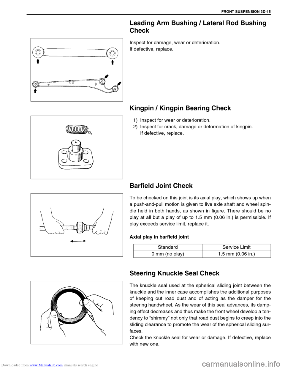
Leading Arm Bushing / Lateral Rod Bushing
Check
Inspect for damage, wear or deterioration.
If defective, replace.
Kingpin / Kingpin Bearing Check
1) Inspect for wear or deterioration.
2) Inspect for crack, damage or deformation of kingpin.
If defective, replace.
Barfield Joint Check
To be checked on this joint is its axial play, which shows up when
a push-and-pull motion is given to live axle shaft and wheel spin-
dle held in both hands, as shown in figure. There should be no
play at all but a play of up to 1.5 mm (0.06 in.) is permissible. If
play exceeds service limit, replace it.
Axial play in barfield joint
Steering Knuckle Seal Check
The knuckle seal used at the spherical sliding joint between the
knuckle and the inner case accomplishes the additional purposes
of keeping out road dust and of acting as the damper for the
steering handwheel. As the wear of this seal advances, its damp-
ing effect decreases and thus make the front wheel develop a ten-
dency to “shimmy” not only that road dust begins to creep into the
sliding clearance to promote the wear of the spherical sliding sur-
faces.
Check the knuckle seal for wear or damage. If defective, replace
with new one.
Standard Service Limit
0 mm (no play) 1.5 mm (0.06 in.)
Page 189 of 687
Downloaded from www.Manualslib.com manuals search engine 3D-16 FRONT SUSPENSION
Wheel Disc, Nut and Bearing Check
1) Inspect each wheel disc for dents, distortion and cracks.
Disc in badly damaged condition must be replaced.
2) Check wheel nuts for tightness and as necessary, retighten
them to specification.
Tightening torque
Wheel nuts
(a) : 95 N·m (9.5 kg-m, 69.0 lb-ft)
3) Check wheel bearing for wear. After retightening lock nut to
specified torque, apply dial gauge to wheel hub center and
measure thrust play.
Wheel bearing thrust play limit
: 0.05 mm (0.002 in)
When measurement exceeds limit, replace bearing.
4) By rotating wheel actually, check wheel bearing for noise and
smooth rotation. If defective, replace bearing.
Page 192 of 687
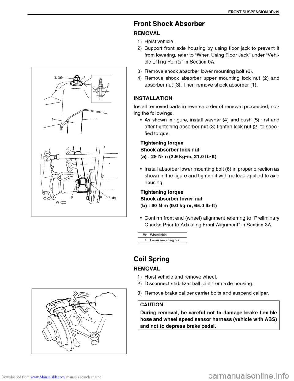
Downloaded from www.Manualslib.com manuals search engine FRONT SUSPENSION 3D-19
Front Shock Absorber
REMOVAL
1) Hoist vehicle.
2) Support front axle housing by using floor jack to prevent it
from lowering, refer to “When Using Floor Jack” under “Vehi-
cle Lifting Points” in Section 0A.
3) Remove shock absorber lower mounting bolt (6).
4) Remove shock absorber upper mounting lock nut (2) and
absorber nut (3). Then remove shock absorber (1).
INSTALLATION
Install removed parts in reverse order of removal proceeded, not-
ing the followings.
As shown in figure, install washer (4) and bush (5) first and
after tightening absorber nut (3) tighten lock nut (2) to speci-
fied torque.
Tightening torque
Shock absorber lock nut
(a) : 29 N·m (2.9 kg-m, 21.0 lb-ft)
Install absorber lower mounting bolt (6) in proper direction as
shown in the figure and tighten it with no load applied to axle
housing.
Tightening torque
Shock absorber lower nut
(b) : 90 N·m (9.0 kg-m, 65.0 lb-ft)
Confirm front end (wheel) alignment referring to “Preliminary
Checks Prior to Adjusting Front Alignment” in Section 3A.
Coil Spring
REMOVAL
1) Hoist vehicle and remove wheel.
2) Disconnect stabilizer ball joint from axle housing.
3) Remove brake caliper carrier bolts and suspend caliper.
W: Wheel side
7. Lower mounting nut
CAUTION:
During removal, be careful not to damage brake flexible
hose and wheel speed sensor harness (vehicle with ABS)
and not to depress brake pedal.